
Device for connecting an end piece to an element

a technology for end pieces and components, applied in the direction of couplings, pipe elements, mechanical apparatus, etc., can solve the problems of high cost of maintenance, storage, stock management, and high cost of manufacturing of couplings, and achieve the effect of simple structure and easy manufacturing

Inactive Publication Date: 2004-07-27
LEGRIS
View PDF14 Cites 24 Cited by
  • Summary
  • Abstract
  • Description
  • Claims
  • Application Information

AI Technical Summary

Benefits of technology

It would therefore be advantageous to have a coupling device that is simple in structure, easy to manufacture, and inexpensive.
As a result, the coupling device is simple in structure, making use of a small number of parts while nevertheless achieving coupling that is similar in effectiveness to the coupling provided by ball couplings, in particular.
This makes it possible to provide coupling devices in which the female portion is adapted to receive a plurality of male endpieces, and to provide interchangeable bushings each adapted to a particular type of male endpiece. Inexpensive adaptors can thus be made for connecting together two elements of a circuit corresponding to two different types of coupling device.

Problems solved by technology

Nevertheless, those couplers are of complex structure involving a large number of parts.
As a result, as well as being heavy, the various components of the coupler are lengthy to assemble, and manufacture thereof is relatively expensive in general terms.
Given the price of these couplers, that leads to relatively high cost for maintenance, storage, and stock management.

Method used


Image

  • Device for connecting an end piece to an element
  • Device for connecting an end piece to an element
  • Device for connecting an end piece to an element

Examples


Embodiment Construction

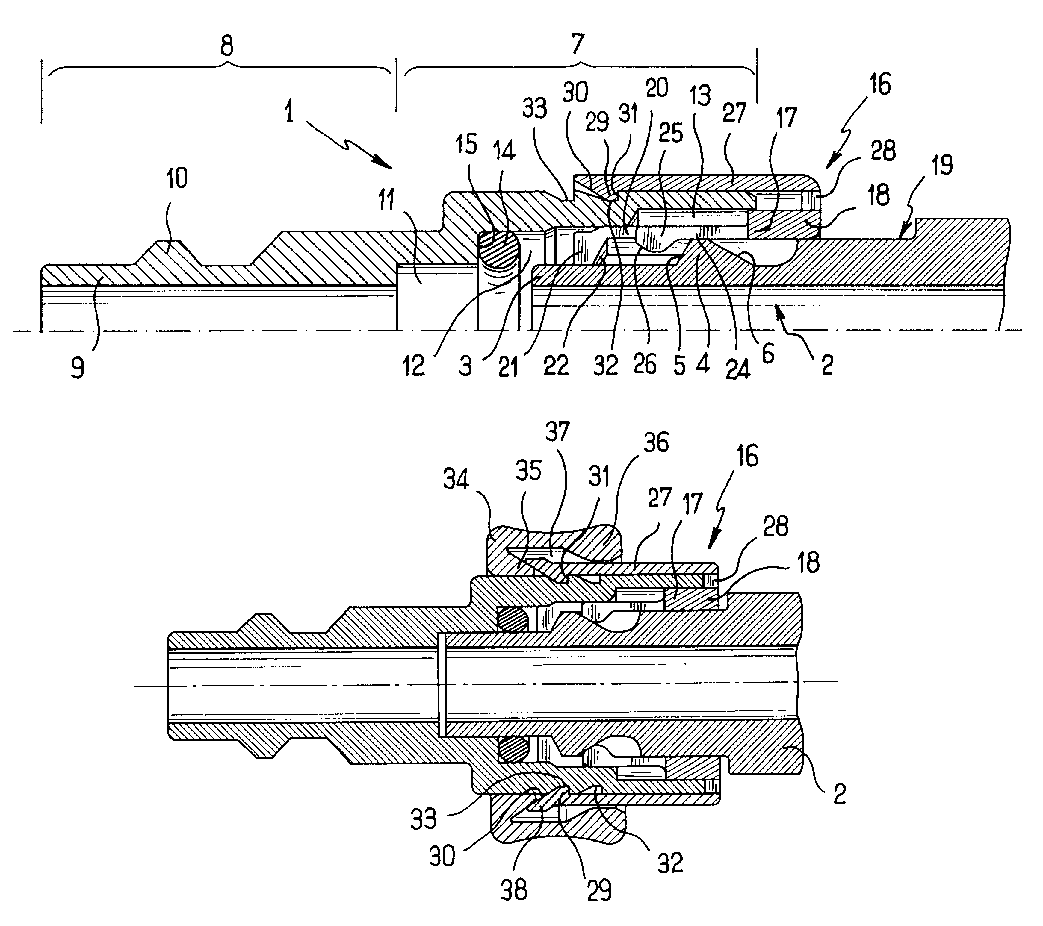
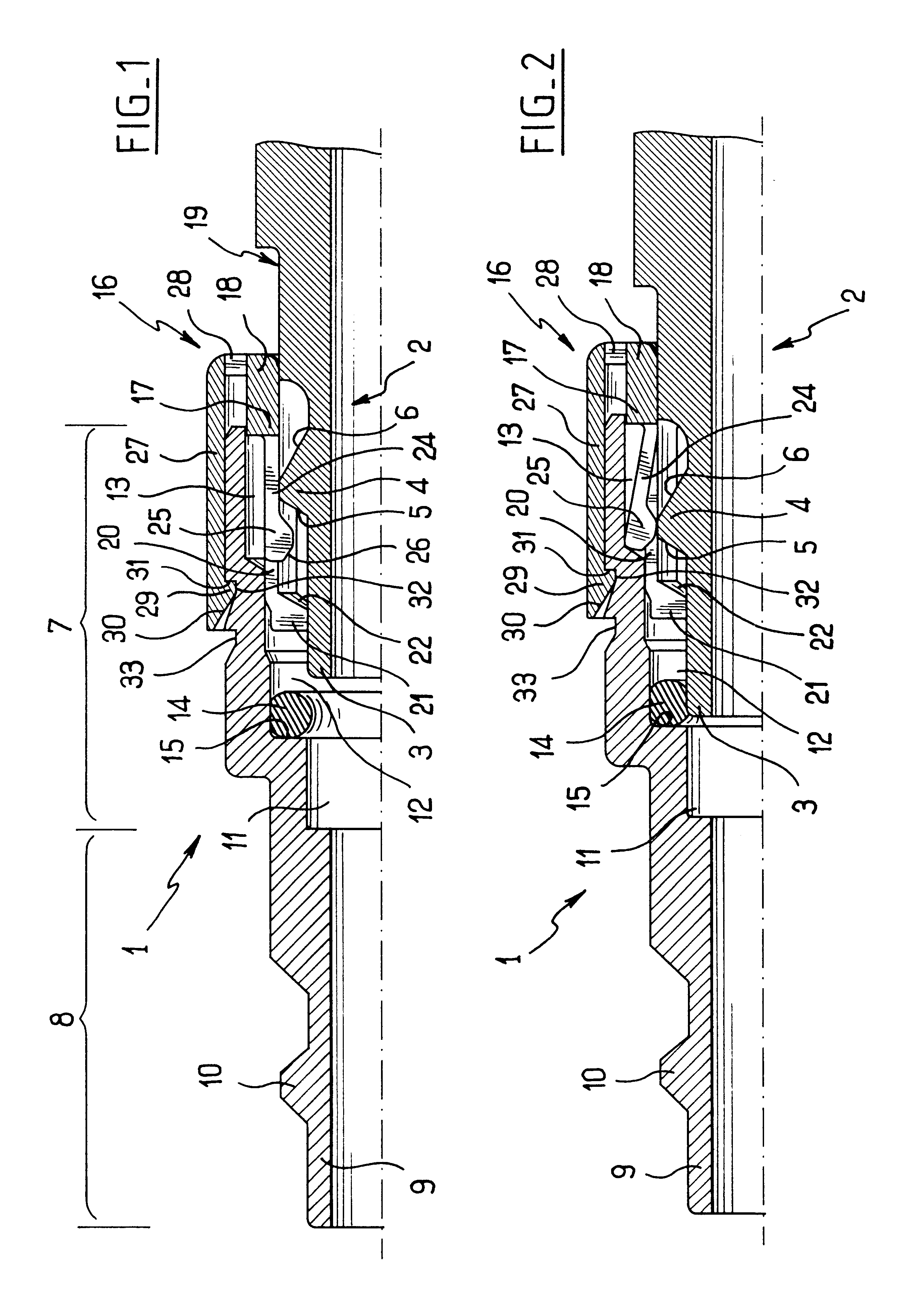
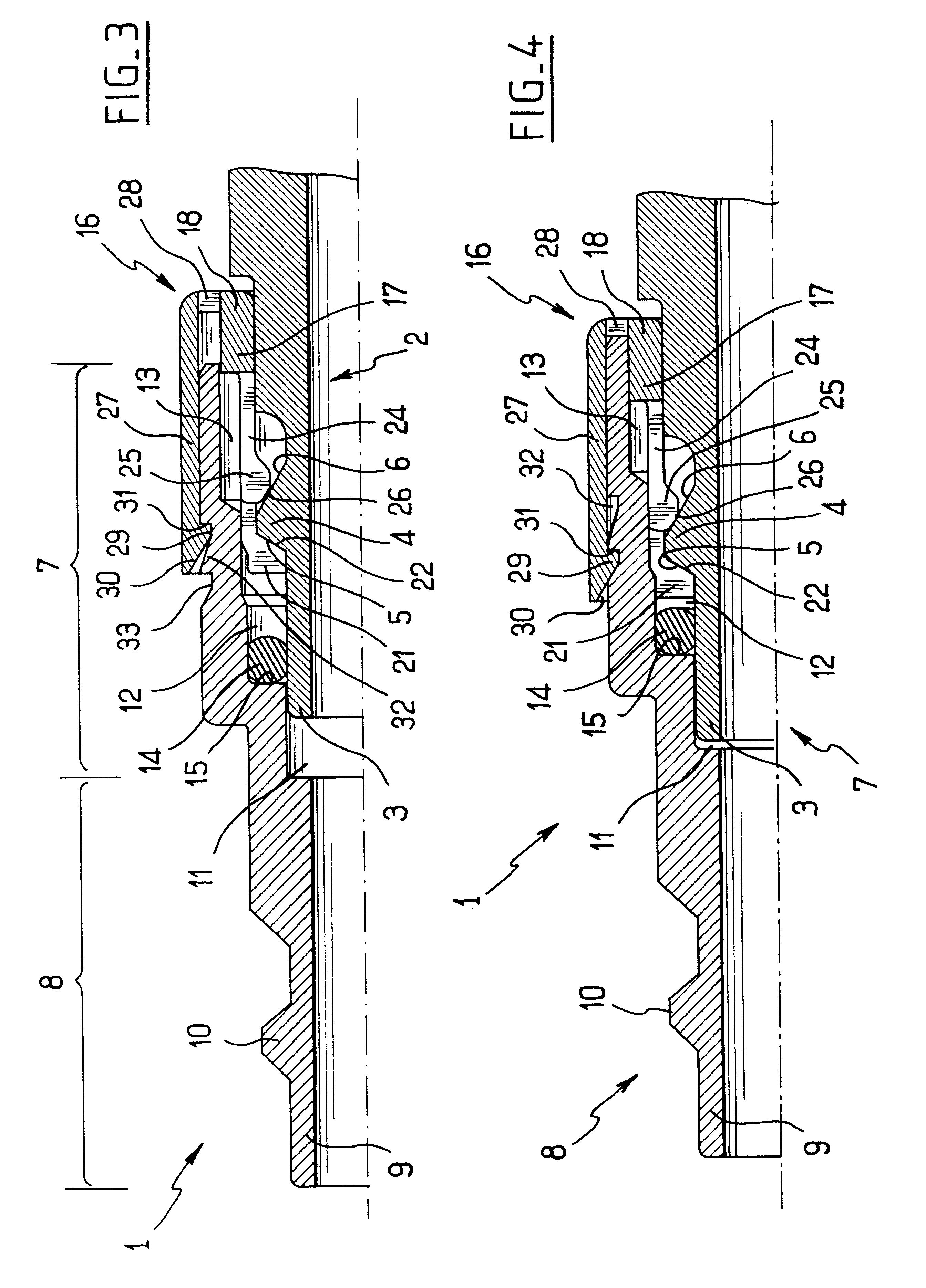
The present invention is described below with reference to the figures in a particular application to an adaptor given overall reference 1 enabling a male tubular endpiece given overall reference 2 and corresponding to a first type of coupling, to be coupled with a female portion (not shown) corresponding to a second type of coupling.

The male endpiece 2 is tubular in shape and has a free end portion 3 provided on the outside with an annular bead 4 laterally defined by front and rear surfaces 5 and 6 of frustoconical shape. The terms "front" and "rear" are used relative to the direction in which the male endpiece 2 is inserted in the female portion 7.

The adaptor 1 has a female portion given overall reference 7 which is arranged to receive the male endpiece 2 and which is described in greater detail below, and a tubular male portion 8 having, in this case, a free end portion 9 provided on the outside with an annular bead 10, which end portion and bead are arranged to be received in th...


PUM


Abstract

A coupling device for coupling an endpiece to a member, comprises a female portion for receiving the endpiece, and a bushing mounted to slide in the female portion and possessing one end projecting from the female portion and provided with at least one blocking member for blocking the bushing either in a pushed-in, locking position or pulled-back, unlocking position, and an opposite end provided both with front abutment elements for coming into abutment with an annular bead of the endpiece, and rear abutment elements for coming into abutment with the bead so that when the bushing is in its unlocking position, the rear abutment elements are movable by the annular abutment between a position in which they project towards the inside of the bushing and a retracted position, and when the bushing is in its locking position, the rear abutment elements are held in their projecting position.

Description

The present invention relates to a coupling device usable in particular in circuits for transporting fluids under pressure in order to provide a quick coupling between two circuit elements such as two pipes or such as a pipe and a member that delivers or receives fluid.Ball couplers are known comprising a male tubular endpiece having an annular external bead and a female tubular endpiece for receiving the male tubular endpiece, the endpieces being designed for being associated with respective elements of the circuit. The male endpiece is held in the female endpiece by means of balls which are pressed by locking means into abutment behind the annular bead.In general, the locking means comprise a ball-holding cage mounted via one end on the female endpiece to extend beyond said endpiece, and a ring mounted on the holding cage to move axially between first and second positions. The ring has inside camming surfaces arranged in such a manner that when the ring is in its first position, t...

Claims


Application Information

Patent Timeline
IPC IPC(8): F16L37/00F16L37/098
CPCF16L37/0982F16L37/0985
Inventor LE CLINCHE, PASCAL
Owner LEGRIS
Learn More