
Product vending

a product vending and product technology, applied in the field of product vending, can solve the problems of limited product range, unsuitable prior art dispensing mechanism, and large volume of particular products to be dispensed such as reams of paper or other media on which printing is to be performed,

Inactive Publication Date: 2004-07-06
MIHI LLC
View PDF5 Cites 132 Cited by
  • Summary
  • Abstract
  • Description
  • Claims
  • Application Information

AI Technical Summary

Benefits of technology

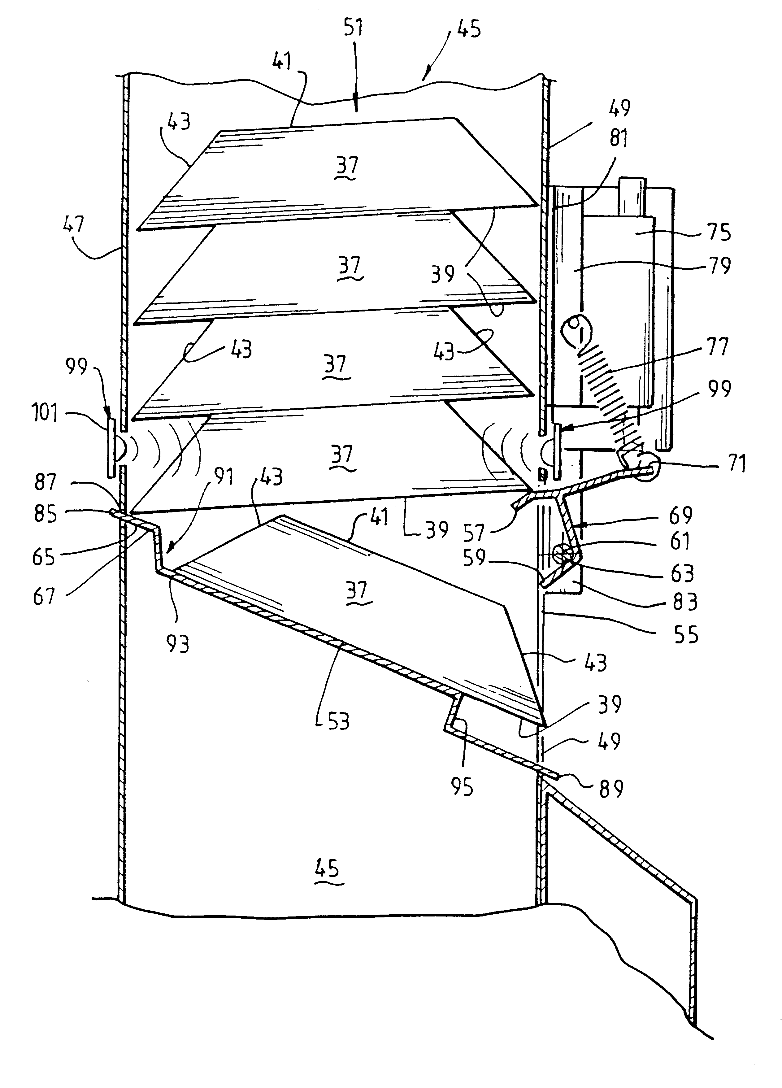
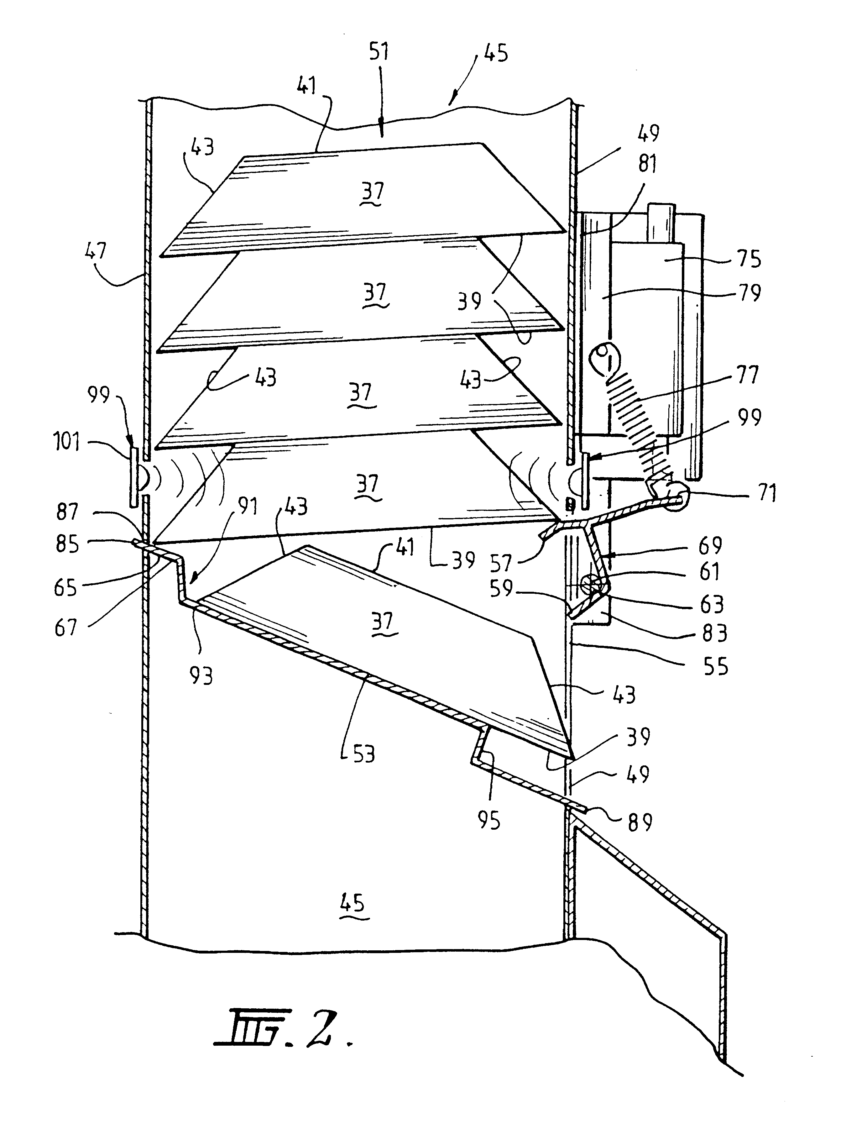
It is particularly preferred that said multiple height chute be a single chute with bays for each module and wherein the plurality of discharge openings be coverable by respective removable wall plates, that said plurality of first tongues and said second tongues be removable, and that said inclined ramps be removable, whereby a product vendor can choose to utilise the whole of the chute for one group of product in a range, or can utilise the chute for a plurality of different product groups in a range, thereby permitting multiple groups of products to be stacked in said chute and user selected for vending by operation of the corresponding first tongue and second tongue.
It is particularly preferred that said ramp be swingable about its upper region so that when loading fresh product into said chute, said ramp can be swung by its lowermost part swinging upwardly to a generally horizontal position thereby closing the chute at the bottom of the chute and inhibiting against mis-oriented product falling through the chute and being discharged from said product discharge opening.
It is particularly preferred that said multiple height chute be a single chute with bays for each module and wherein the plurality of discharge openings be coverable by respective removable wall plates, said plurality of first tongues and said second tongues be removable, and that said inclined ramps be removable, whereby a product vendor can choose to utilise the whole of the chute for one group of product in a range, or can utilise a chute for a plurality of different product groups in a range, thereby permitting multiple groups of product to be stacked in said chute and user selected for vending by operation of the corresponding first tongue and second tongue.
It is particularly preferred that said ramp be swingable about its upper region so that when loading fresh product into said chute, said ramp can be swung from its lowermost part upwardly to a generally horizontal position thereby closing the chute at the bottom of the chute and inhibiting against mis-oriented product falling through the chute and being discharged from said product discharge opening.
the spacing between said tongue and said stop being such that a single product can be supported on the floor in said space and prevented from falling by gravity from said floor by said stop, and wherein said tongue is advanceable into said path to prevent movement of the next product in said path, so that when product is to be vended said stop can be moved away from the end of the floor thereby allowing the product to fall by gravity and to be vended, and to permit product held in said path by said tongue, and so that after vending said stop can be returned to the end of the floor and the tongue retreated thereby allowing the next product to move into said space between said tongue and said stop whereupon said tongue can then be advanced between the next product and the succeeding product making the machine ready for future vending.
Most preferably said end wall is pivoted near the top of said storage bin so it can swing from a position where it is at the end of said floor to a position away from said floor.

Problems solved by technology

Hitherto, the vending mechanisms within such vending machines have limited the product range which can be stocked as the vending mechanisms have occupied a considerable space within the vending machine.
Further, particular product which is to be dispensed such as reams of paper or other media on which printing is to be performed is relatively bulky and relatively heavy compared to, for example, printer cartridges, particularly inkjet printer cartridges.
Thus, if a vending machine is to dispense heavy articles of this type, the known prior art dispensing mechanisms have been unsuitable as the vending mechanisms cannot handle the large relative weight of such articles.

Method used


Image

  • Product vending
  • Product vending
  • Product vending

Examples


Embodiment Construction

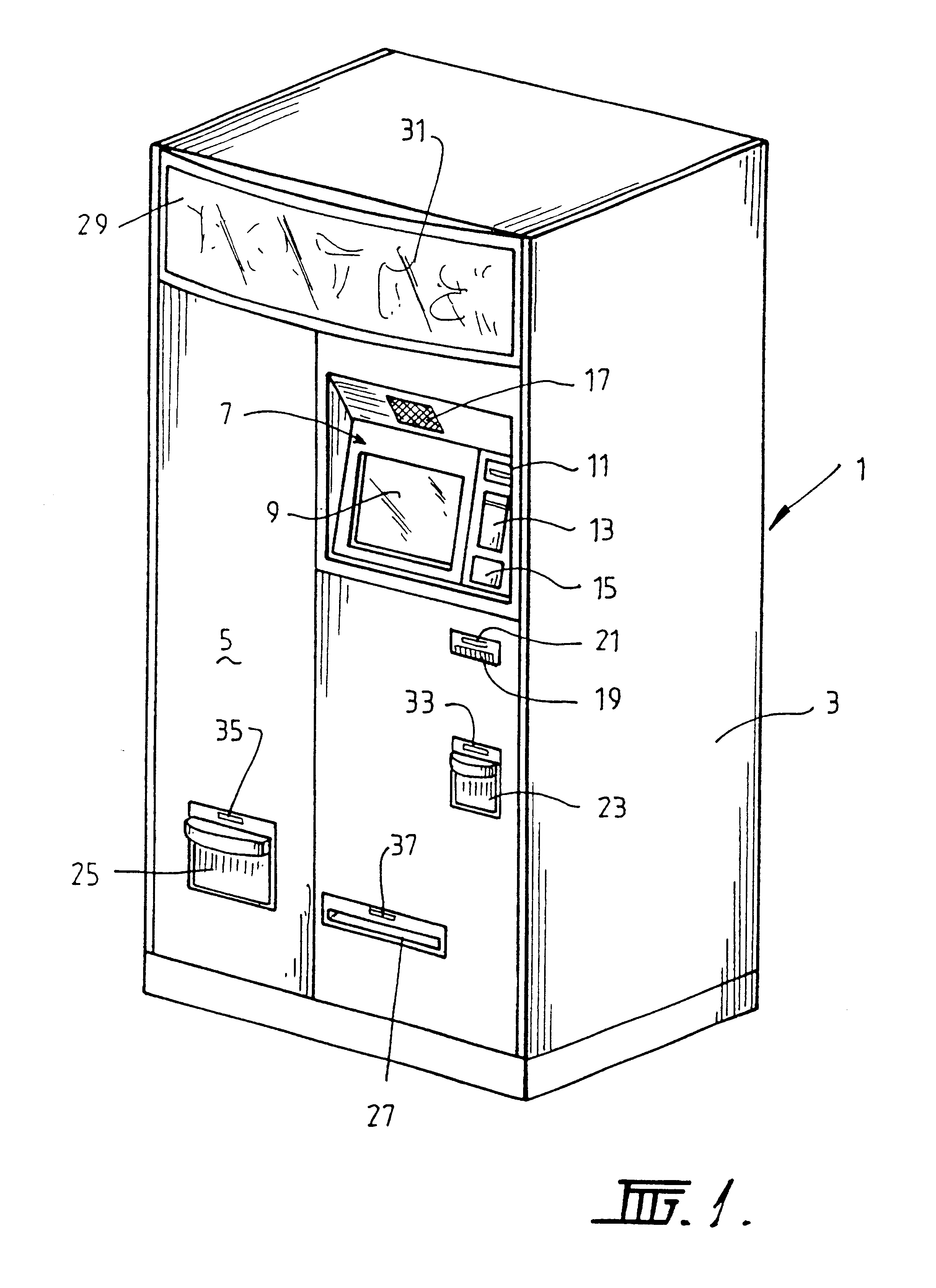
Referring firstly to FIG. 1, there is shown a vending machine 1 having a cabinet 3 made from sheet metal or other suitable material. The cabinet 3 is generally rectangular in footprint and stands upright. The front face 5 is provided with a user-interactive panel 7 which is preferably on a vertically inclined face. Panel 7 has a monitor screen 9 on which can be displayed messages and instructions and also a touch keyboard for alphanumeric data entry. In the upper right hand corner of panel 7 there is provided a motorised card reader 11 for reading credit cards and other similar cards. Below the card reader 11 is a "secure" PIN pad 13 for data entry of PIN numbers for a credit card introduced into the card reader 11. Mounted below the PIN pad 13 is a bar code scanning device 15. This can be used to scan bar code on existing product which the purchaser may already have on hand. In this way, particular product items can be selected by bar code scanning the bar code on the product held ...


PUM


Abstract

A dispensing mechanism is provided for flat faced products. The products are supported in a storage chute between a first upright wall and a second upright wall, stacked one on top of another. The products are supported in the chute by a support surface and a first tongue. Products are dispensed by retracting the first tongue allowing a lowermost product to fall onto a second tongue. The first tongue is advanced to be under the next highermost product in the chute. The second tongue is then retracted allowing the lowermost product to fall onto the support surface and pass through a discharge opening. In a further embodiment, flat faced products are stacked vertically side-by-side on a slightly inclined floor. The products move horizontally to one side to be dispensed. A tongue and a moveable stop are mounted at that side. The spacing between the tongue and the stop is generally equal the thickness of the product. The product can be dispensed by retracting the tongue allowing all of the products to move to that side and making the mechanism ready to dispense the next product. The mechanism includes a sensor to detect when a dispensed product is removed from a delivery bin, and a process to credit a customer's account for a product not removed from the delivery bin.

Description

This invention relates to product vending and relates particularly but not exclusively to product vending apparatus and parts therefor suitable for vending high cost products such as consumables for computer printers.DESCRIPTION OF PRIOR ARTHitherto, it has been known to provide vending apparatus for dispensing high cost product such as consumables in computer printing machines. Typical examples of prior systems are disclosed in our co-pending international patent applications nos. PCT / AU93 / 00416 (WO94 / 04446), and PCT / AU95 / 00154 (WO95 / 26004). The disclosures in those documents are herein incorporated by reference. PCT / AU93 / 00416 relates to a vending machine which facilitates recycling of complex articles, such as printer and toner cartridges. PCT / AU95 / 00154 discloses an electronic catalogue device and system for enabling remote ordering of goods / services.With the ever-increasing models of printers on the market there is an increase in the number of products which are specific to par...

Claims


Application Information

Patent Timeline
Patent Type & Authority Patents(United States)
IPC IPC(8): G07F11/04G07F11/06G07F11/16
CPCG07F11/06G07F11/16G07F11/163
Inventor COOKE, BRIANGRONDMAN, MARKJENKINS, ALANMUSSETT, GERRYCAMERON, MAGNUSSMITH, GOWER
Owner MIHI LLC
Learn More