
Energy regulation system for an electrical power supply bus

a technology of energy regulation system and power supply bus, which is applied in the direction of secondary cell servicing/maintenance, process and machine control, instruments, etc., can solve the problems of unautonomous system of this kind, inability to control the fine regulation of battery charging, and inability to be truly reliable, so as to reduce the risk of convergence

Inactive Publication Date: 2004-06-01
ALCATEL LUCENT SAS
View PDF5 Cites 30 Cited by
  • Summary
  • Abstract
  • Description
  • Claims
  • Application Information

AI Technical Summary

Benefits of technology

Enables autonomous and reliable regulation of both bus voltage and battery charging without relying on the onboard computer, optimizing energy use and reducing weight and cost by eliminating the need for complex electronic chargers.

Problems solved by technology

First of all, it cannot effect fine regulation of the charging of the battery in accordance with standard battery charging methods, in other words it cannot effect some of the charging at a constant current and further charging (the end of charging) at a constant voltage, i.e. with varying current.
As the computer is itself supplied with power by the power supply bus, a system of this kind is not autonomous and cannot be truly reliable.

Method used


Image

  • Energy regulation system for an electrical power supply bus
  • Energy regulation system for an electrical power supply bus
  • Energy regulation system for an electrical power supply bus

Examples


Embodiment Construction

Components are identified by the same reference number in all the figures in which they are shown.

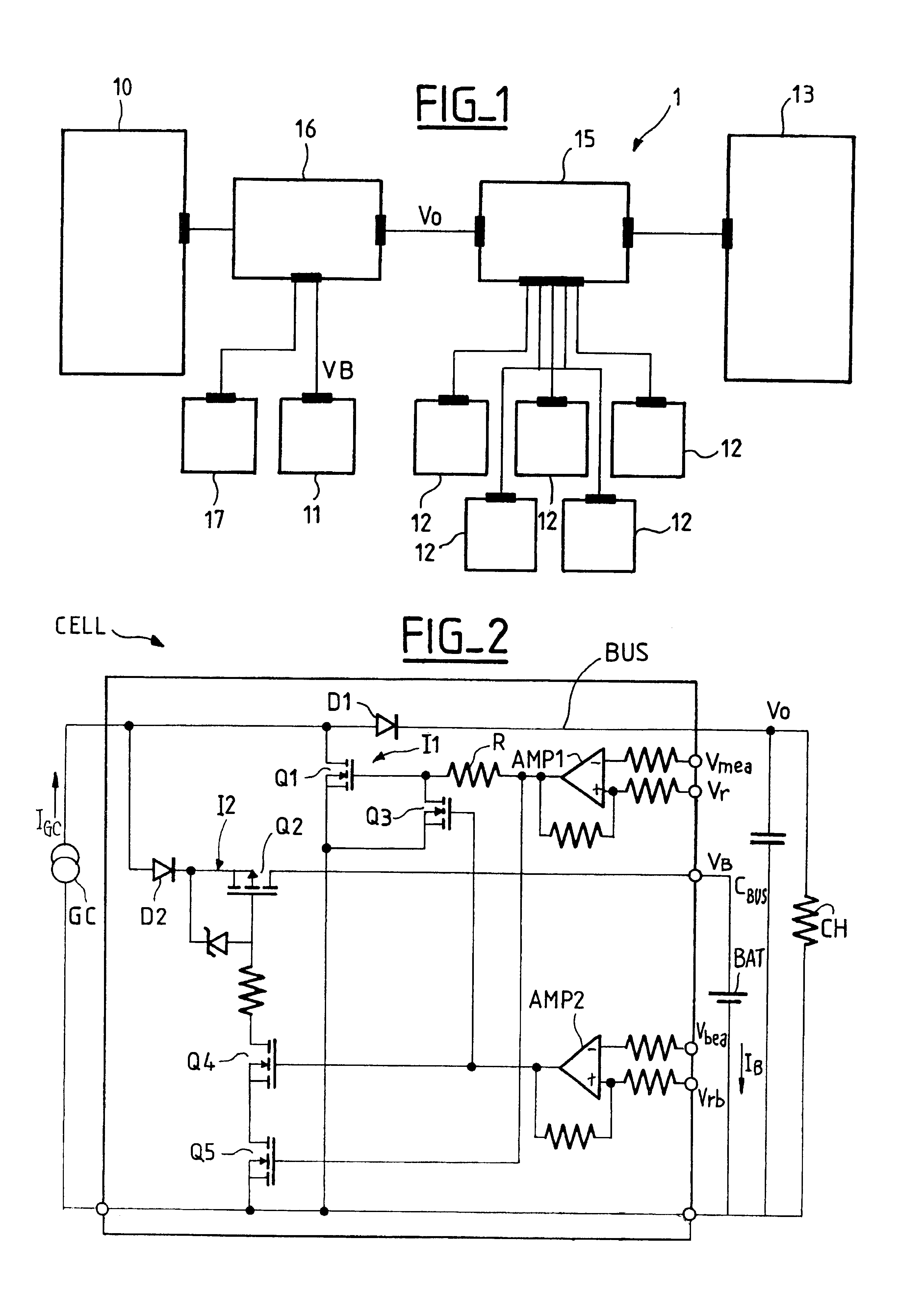
FIG. 1 shows the topology of a power supply bus 1 used on board a satellite. The power supply bus 1 includes a solar generator 10 using solar energy recovered from solar panels (not shown) of the satellite and an energy storage unit in the form of a battery 11. These two components form the power supply that supplies electrical energy to the payload 13 and to various onboard functions 12 of the satellite necessary for its operation, such as propulsion, attitude control, ground link, thermal control, etc.

This energy is distributed by an energy distributor unit 15 connected to all the above components and receiving a regulated voltage V.sub.0 from an energy regulator unit 16 connected to the generator 10 and to the battery 11.

A battery management unit 17 manages the battery 11 which has a charging voltage V.sub.B.

The regulator unit 16 is the core of the power supply bus 1 in that it distr...


PUM


Abstract

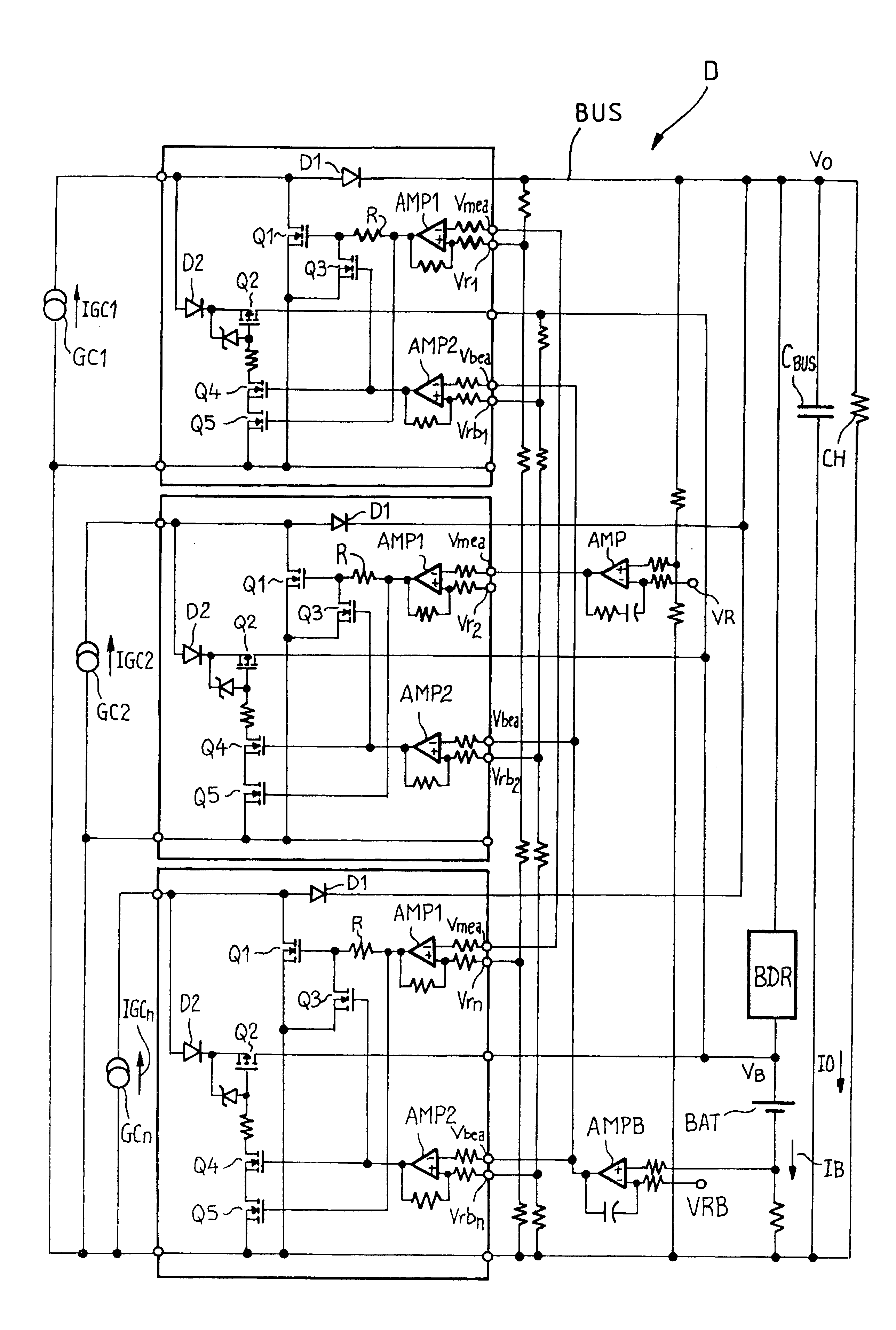
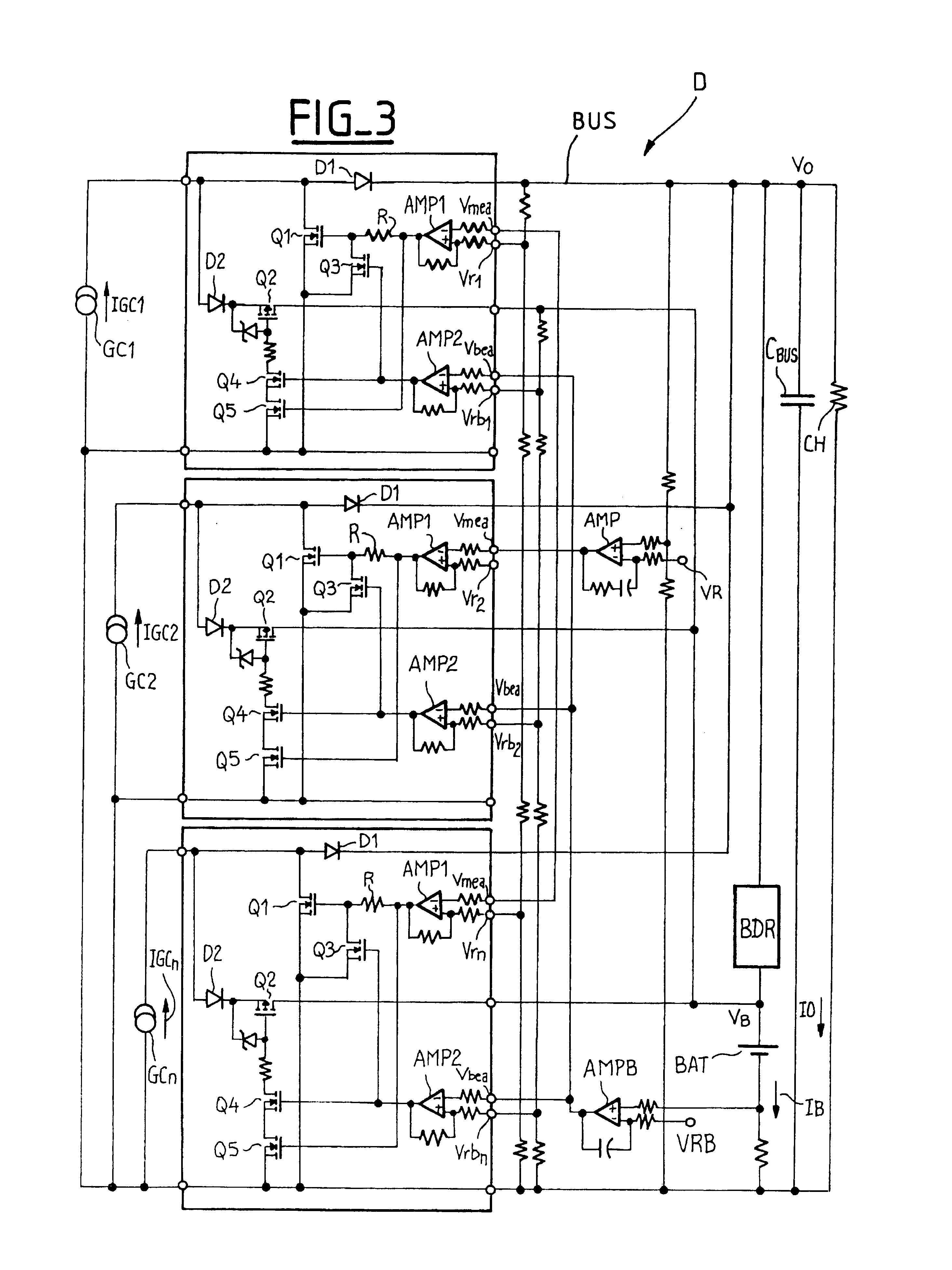
The present invention relates to an electrical energy regulator system for a power supply bus, the system including:an electrical energy storage unit,a solar generator having a plurality of cells,a system for regulating the bus power supply voltage adapted to impose on each cell one of the following three states:a first state in which the bus is supplied with current,a second state in which the storage unit (BAT) is supplied with current, anda third state in which the cell is shunted,the cells being divided by the bus voltage regulator system into:a first group in which at least one cell supplies power to the bus and one cell is assigned to regulation of the voltage of the bus and is in its first state only when maintaining a nominal bus voltage requires a top-up of current, anda second group in which at least one cell is either in a second state or in a third state, as a function of a required charging current of the storage unit, the number of cells in the second state being a function of the required charging current.The system further includes a system means for regulating the charging of the storage unit which assign at least one cell of the second group to supplying power to the storage unit (BAT) and one cell of the second group to regulating the voltage of the storage unit, the storage unit charging voltage regulator cell being in its second state only when maintaining a nominal charging voltage requires a top-up of current.

Description

The present invention relates to an energy regulation system for an electrical power supply bus, in particular of the type used on board a satellite.The network to be supplied with power on board a satellite, comprising the payload and the service platform of the satellite itself, is supplied with power from the following two energy sources, via a power supply bus:a solar generator (using solar energy recovered by solar panels of the satellite), which converts light energy into electrical energy, and generally comprises a plurality of cells, andan electrical energy storage unit comprising one or more batteries for storing a portion of the electrical energy from the solar generator and converting it into electrochemical energy that is available in the form of electrical energy during eclipses or consumption peaks.As the person skilled in the art is well aware, the supply buses used on board satellites operate at a predetermined regulated voltage, generally 50 V or 100 V. This regulat...

Claims


Application Information

Patent Timeline
Patent Type & Authority Patents(United States)
IPC IPC(8): H02J7/35
CPCH02J7/35Y10S323/906
Inventor CAPEL, ANTOINELECOINTE, PASCAL
Owner ALCATEL LUCENT SAS
Learn More