
Front axle arrangement for a heavy vehicle

a front axle and heavy vehicle technology, applied in the direction of roofs, electric propulsion mountings, jet propulsion mountings, etc., can solve the problems of low resistance to bending and torsion, not entirely satisfactory riding comfort, and not being able to achieve riding comfort and vehicle running characteristics

Inactive Publication Date: 2004-05-18
SCANIA CV AB
View PDF9 Cites 46 Cited by
  • Summary
  • Abstract
  • Description
  • Claims
  • Application Information

AI Technical Summary

Benefits of technology

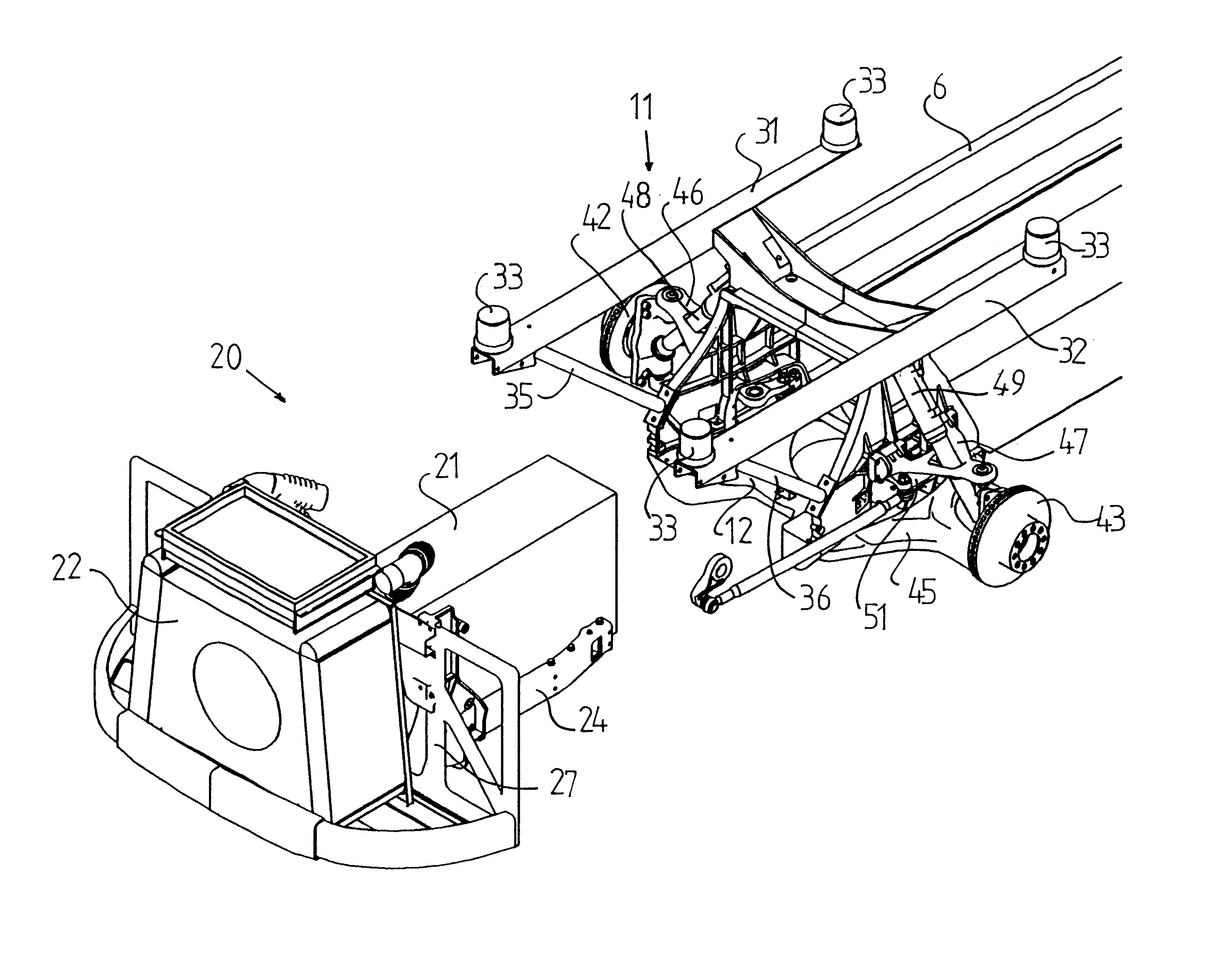
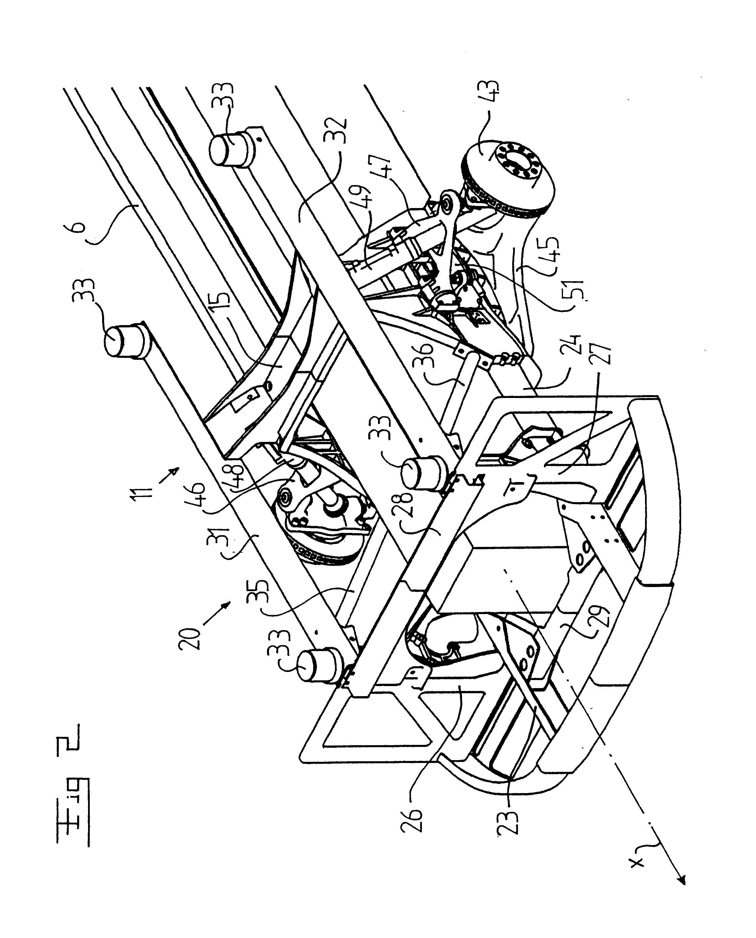
Such a front axle unit incorporating a box-like frame structure which supports vital components of the vehicle in the region of the front axle makes it possible to create a unit which forms a front axle module which can be used for many different vehicle variants. The box-like structure also means that the front axle unit according to the invention is so constructed as to be, in all essentials, self-supporting and designed to absorb at least substantially all the vertical forces which act upon the front wheels.
According to a further embodiment of the invention, the engine unit is intended to be connected via a driveshaft to a gearbox which is situated at a distance from the engine unit and adjacent to powered rear wheels of the vehicle. This provides the vehicle with a favourable weight distribution.

Problems solved by technology

Relatively low resistance to bending and torsion does entail, however, certain problems with regard to riding comfort and vehicle running characteristics.
The chassis element having relatively low resistance to torsion and the wheel axles being made of steel result in not entirely satisfactory riding comfort, particularly on long journeys and on good roads.
Nor is it possible for riding comfort and vehicle running characteristics to be improved to any appreciable extent by more sophisticated suspension systems.
Conventional frame side members and steel wheel axles result in any road surface unevenness being propagated in the support device and having adverse effects on substantially the whole vehicle.
The conventional superstructure of a heavy vehicle also has the disadvantage of its manufacture being relatively expensive because such a design involves many different components which cannot be standardised for different vehicle variants.
Such a conventionally constructed heavy vehicle also requires a relatively large amount of assembly work.

Method used


Image

  • Front axle arrangement for a heavy vehicle
  • Front axle arrangement for a heavy vehicle
  • Front axle arrangement for a heavy vehicle

Examples


Embodiment Construction

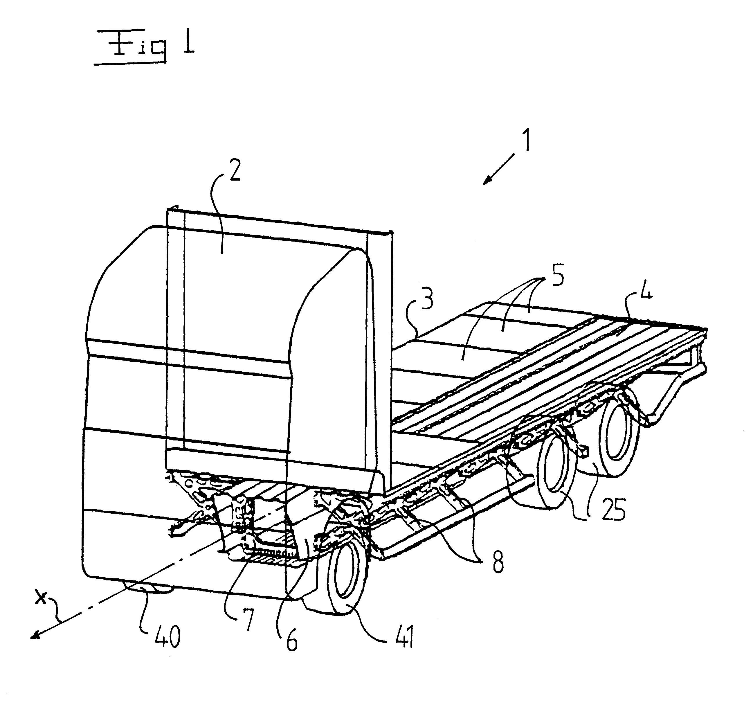
FIG. 1 depicts schematically a heavy vehicle 1 with a driver's cab 2 and a load surface 3 which consists of a corrugated metal sheet 4 and panels 5 arranged on the metal sheet 4. FIG. 1 depicts a heavy vehicle in the form of a truck but it should be noted that the invention is also applicable to other types of heavy vehicle, e.g. buses.

The vehicle 1 incorporates a chassis element 6 which extends substantially parallel with the vehicle's longitudinal axis x in the vehicle's normal direction of forward movement. As indicated in FIG. 1, the chassis element 6 has a box-like shape and is substantially quadrilateral as viewed in the direction of the longitudinal axis x. The chassis element 6 is made of relatively thin sheetmetal. The chassis element 6 also incorporates a number of support frames 7 which have a central aperture and are distributed along the length of the chassis element 6. FIG. 1 shows only one such support frame 7. On each side of the chassis element 6, outside each suppo...


PUM


Abstract

The invention relates to a front axle arrangement for a heavy vehicle, e.g. a freight vehicle. The vehicle incorporates a number of wheels (42, 43) which bear the vehicle, and an engine unit (20) for the vehicle's propulsion and a longitudinal chassis element (6) which extends along the vehicle's longitudinal axis in the normal direction of forward movement of the vehicle. The front axle arrangement forms a separate front axle unit (11) incorporating a frame structure (12-15) which is intended to be connected to the longitudinal chassis element, and two of said wheels which are suspended in the frame structure. The front axle unit (11) is intended to bear the engine unit (20) in such a way that the latter extends in through a central aperture of the frame structure (12-15) and can at least partially be extracted from the front axle unit.

Description

BACKGROUND TO THE INVENTION, AND STATE OF THE ARTThe present invention relates to a front axle arrangement for a heavy vehicle and its cooperation with the vehicle chassis and also with the vehicle engine.Heavy vehicles, which here means, for example, trucks, buses and similar freight and utility vehicles, incorporate according to conventional technology a longitudinal chassis element in the form of two frame side members which are connected to one another by means of a number of cross-members. The frame side members extend parallel with one another along substantially the whole length of the vehicle and support vehicle components such as the engine, the driver's cab and a load surface which takes the form of, for example, a load platform or a superstructure. In addition, the vehicle's front and rear axles are suspended in the frame side members.In heavy vehicles such as trucks, the frame side members and the cross-members act as the main loadbearing parts of the vehicle in order to...

Claims


Application Information

Patent Timeline
Patent Type & Authority Patents(United States)
IPC IPC(8): B60G7/02B60G3/20B60G3/18B60K5/00B62D33/02B62D21/02B62D25/20
CPCB60G3/20B60G7/02B60K5/00B62D33/02B60G2200/144B60G2204/128B60G2204/129B60G2204/143B60G2204/148B60G2204/15B60G2204/16B60G2206/011B60G2206/0114B60G2206/60B60G2300/026
Inventor BERGSTROM, AKEWALLIN, PARLINDEN, MICHAELMODAHL, FREDRIKGUSTAVSSON, ANDERSDAVIDSON, GEOFFREY
Owner SCANIA CV AB
Learn More