Apparatus for facilitating reduction of vibration in a work vehicle having an active CAB suspension system

a technology of active suspension system and apparatus, which is applied in the direction of cycle equipment, instruments, tractors, etc., can solve the problems of affecting the ride quality and operator comfort of the work vehicle, affecting the comfort of the operator, and affecting the movement of the cab. , to achieve the effect of reducing vibration

Inactive Publication Date: 2005-05-24
BLUE LEAF I P INC +1
View PDF49 Cites 92 Cited by
  • Summary
  • Abstract
  • Description
  • Claims
  • Application Information

AI Technical Summary

Benefits of technology

[0016]In another embodiment, the invention relates to an apparatus for determining when a component of a work vehicle experiences vibration above a predetermined threshold and taking an action to reduce the vibration when the vibration is above the predetermined threshold. In addition to the above-described sensor and signal processor, the apparatus further includes an actuator that is coupled to the signal processor and configured to receive the second signal. The actuator is configured to take an action to reduce the vibration to below the predetermined threshold if the second signal indicates that the vibration experienced by the component is above the predetermined threshold.
[0017]The present invention further relates to a method of determining when a component of a work vehicle experiences vibrati...

Problems solved by technology

In a work vehicle that does not include a cab suspension system, the ride quality and operator comfort of the work vehicle is adversely affected by vibrations or movement transmitted from the frame or chassis of the vehicle to the operator's cab.
Movement of the cab can be particularly severe in agricultural and construction equipment vehicles (e.g., tractors, combines, backhoes, cranes, dozers, trenchers, skid-steer loaders, etc.) because such vehicles typically operate on off-road surfaces or fields having a high level of bumpiness.
Operator comfort may also be adversely affected by the operation of various systems on a work vehicle.
The movement of the cab caused by surface bumps and the operation of vehicle systems cause both qualitative and quantitative problems.
An operator of such a vehicle experiences increased levels of discomfort and fatigue caused by the vibrations.
Productivity is decreased when an operator is forced to rest or shorten the work day, or is unable to efficiently control the work vehicle.
The operator is also less likely to be satisfied with a work vehicle which provides poor ride quality.
Under certain conditions, the frequency and magnitude of cab movement may force the operator to decrease driving speed, further decreasing productivity.
However, performance of passive systems is limited due to design compromises needed to achieve good control at resonance frequencies and good isolation at high frequencies.
Although work vehicles having active cab suspension systems provide improved ride quality and increased operator comfort, the active cab suspension systems neither are designed for nor are capable of eliminating all undesirable vibration and movement experienced within the cabs or by other components of the work vehicles.
As a work vehicle proceeds down a path, the work vehicle (e.g., the chassis of the work vehicle) continually experiences vibration due to variation in the level of the terrain being traversed.
Such vibration may be of sufficient magnitude to cause damage to the work vehicle, in several ways.
If the vibration is significant but does not overly strain the active cab suspension system, the active cab suspension system will shield the operator of the work vehicle from much or all of the vibration, and the operator will likely remain unaware of the magnitude of the vibration.
In this case, although the operator will not physically experience all of the vibration, the vibra...

Method used


Image

  • Apparatus for facilitating reduction of vibration in a work vehicle having an active CAB suspension system
  • Apparatus for facilitating reduction of vibration in a work vehicle having an active CAB suspension system
  • Apparatus for facilitating reduction of vibration in a work vehicle having an active CAB suspension system

Examples


Embodiment Construction

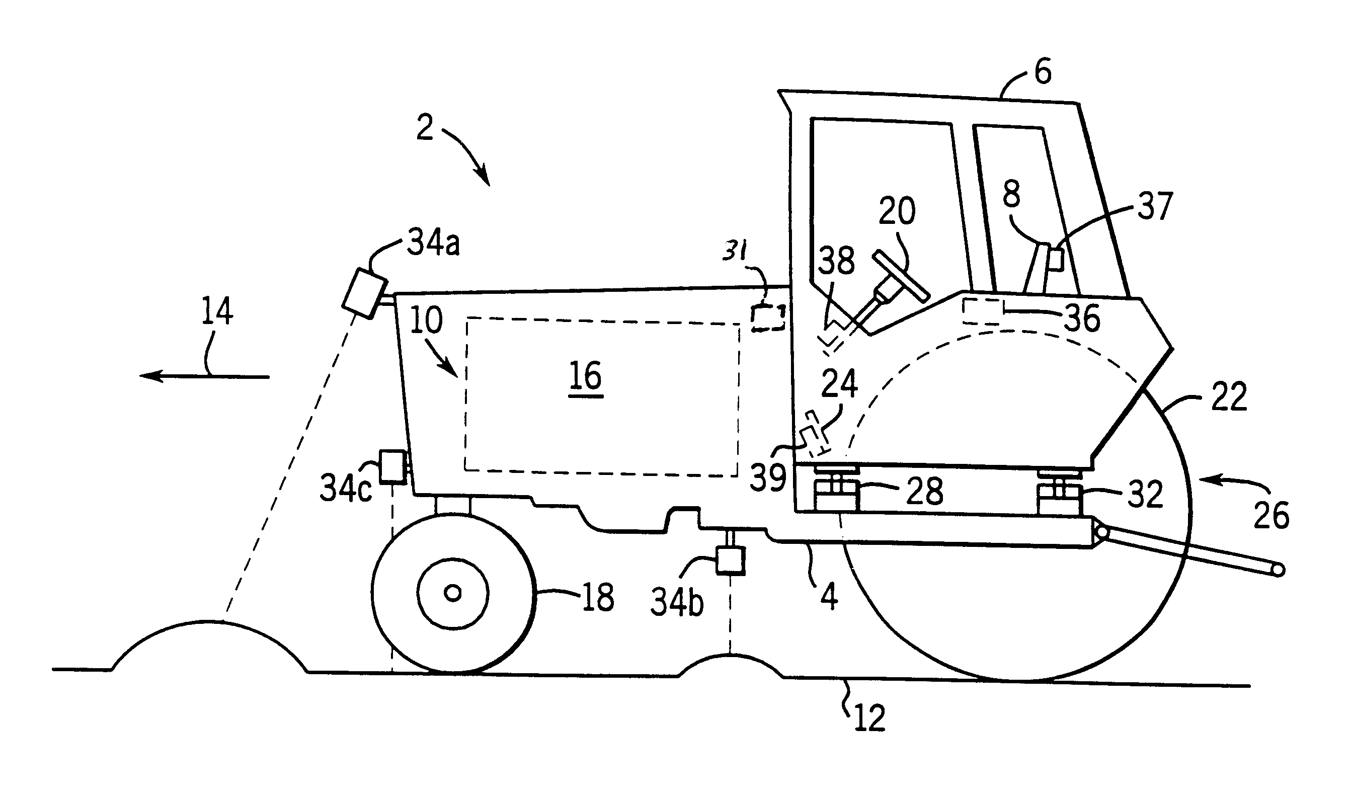
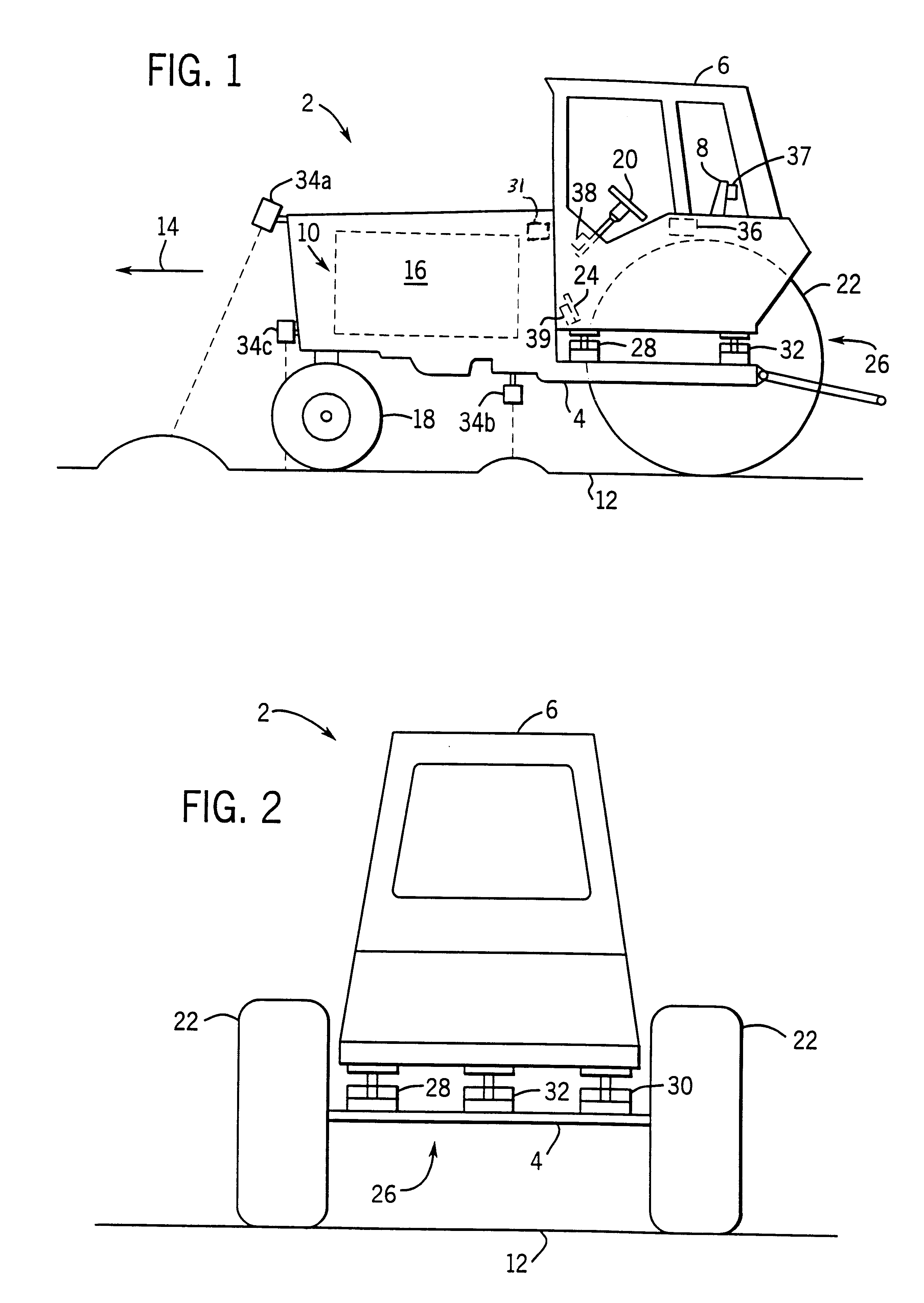
[0034]Referring to FIGS. 1 and 2, a work vehicle 2 (e.g., an agricultural tractor) includes a frame or chassis 4, an operator's cab 6 supported above chassis 4, a seat or dual seats 8 within cab 6, and a propulsion system 10 to propel vehicle 2 along a ground surface 12 in a forward direction 14. Propulsion system 10 includes an engine 16 secured to chassis 4, a transmission (not shown) coupled to engine 16, two driven or non-driven front wheels 18 steered by a steering wheel 20, and two rear wheels 22 driven by engine 16 via the transmission. Brake pedals 24 located in cab 6 operate left and right service brakes (not shown) to provide braking. Cab 6 is supported above chassis 4 by an active cab suspension system (ACS) 26 including two front active vibration isolators 28 and 30 located on opposite sides of cab 6 and a rear isolator 32 centrally located at the rear of cab 6 between wheels 22. The three-point suspension system provides stable control of movement responsive to pitch, r...


PUM


Abstract

An apparatus and method for determining when a component of a work vehicle experiences vibration above a predetermined threshold, and responding to the vibration so that the vibration is reduced below the predetermined threshold. The apparatus, which is in a work vehicle that includes a chassis, an operator's cab and an active cab suspension system, includes a sensor that is configured to sense a quantity representative of the vibration experienced by the component of the work vehicle and to develop a first signal indicative of that quantity. The apparatus also includes a signal processor that is coupled to the sensor and is configured to develop, in response to the first signal, a second signal indicative of whether the vibration experienced by the component is above the predetermined threshold. The apparatus further includes a device that is coupled to the signal processor and, in response to the second signal, is either configured to provide an indication or configured to take an action to reduce the vibration below the predetermined threshold when the vibration is above the predetermined threshold.

Description

FIELD OF THE INVENTION[0001]The present invention relates generally to the field of active suspension systems used in work vehicles. More particularly, the invention relates to an apparatus and method in a work vehicle having an active cab suspension system for determining when a component of the work vehicle experiences vibration above a predetermined threshold and responding to the vibration in a manner intended to reduce the vibration to below the predetermined threshold.BACKGROUND OF THE INVENTION[0002]In a work vehicle that does not include a cab suspension system, the ride quality and operator comfort of the work vehicle is adversely affected by vibrations or movement transmitted from the frame or chassis of the vehicle to the operator's cab. As the work vehicle travels across a surface, movement of the chassis induces the operator's cab to pitch, roll and bounce. Movement of the cab can be particularly severe in agricultural and construction equipment vehicles (e.g., tractors...

Claims


Application Information

Patent Timeline
IPC IPC(8): B60G17/015B60G17/0195B60G17/0165B60G17/018B62D33/06B60G23/00
CPCB60G17/0165B60G17/0195B62D33/0608B60G17/018Y10S180/902B60G2202/32B60G2202/412B60G2202/413B60G2204/162B60G2204/62B60G2300/082B60G2400/102B60G2400/204B60G2400/60B60G2400/61B60G2400/821B60G2400/824B60G2401/16B60G2600/181B60G2600/182B60G2800/019B60G2800/162B60G2800/21B60G2800/214B60G2800/915B60G2800/916B60G2800/95B60G2800/954B60G2800/96
Inventor SCHUBERT, WILLIAM L.
Owner BLUE LEAF I P INC
Why Eureka
Try Eureka