
Safety port needle assembly

a safety port and needle technology, applied in the direction of suction devices, needles infusion, other medical devices, etc., can solve the problems of accidental skin puncture, accidental puncture,

Inactive Publication Date: 2004-04-13
LRP L L C
View PDF14 Cites 125 Cited by
  • Summary
  • Abstract
  • Description
  • Claims
  • Application Information

AI Technical Summary

Benefits of technology

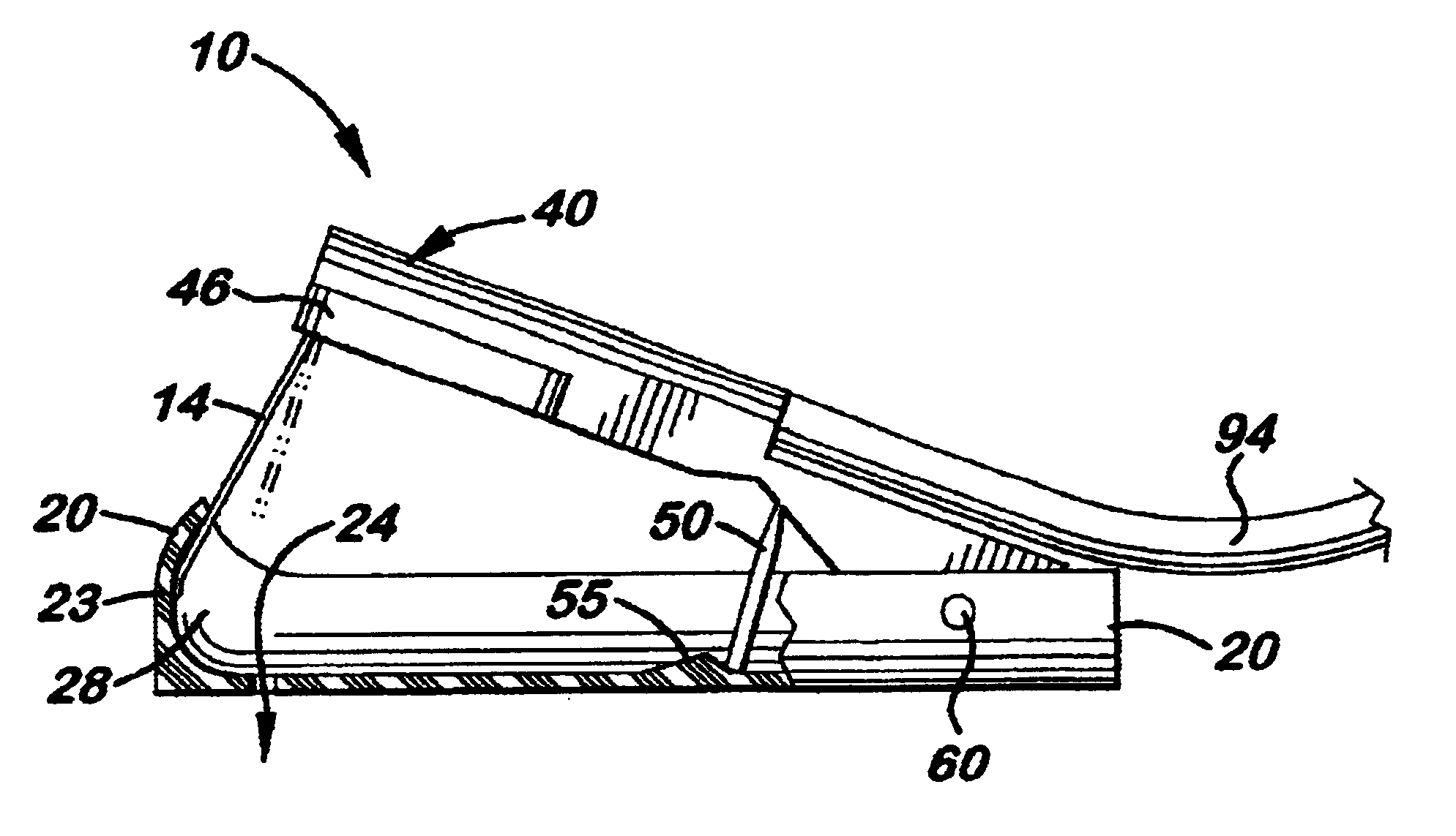
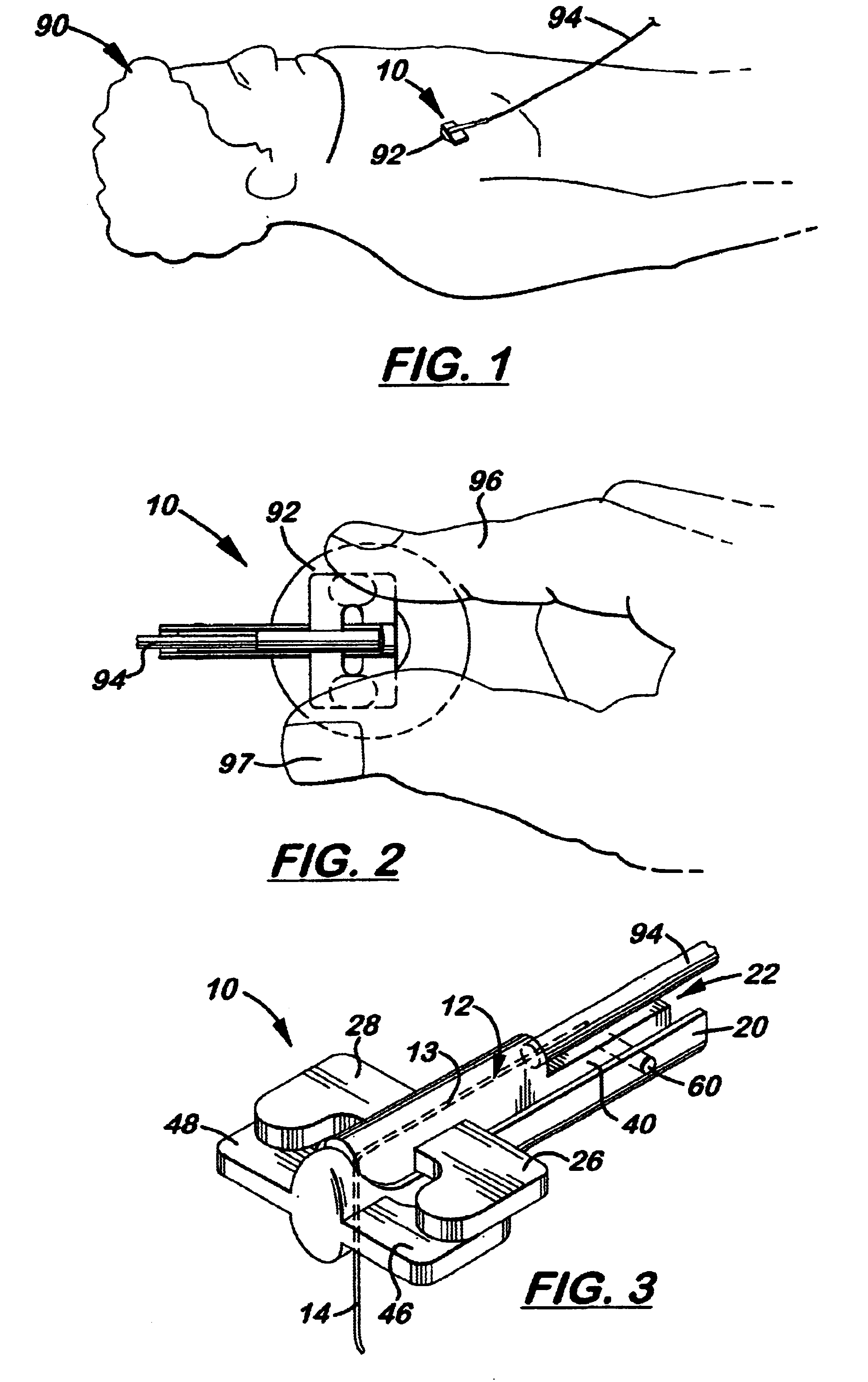
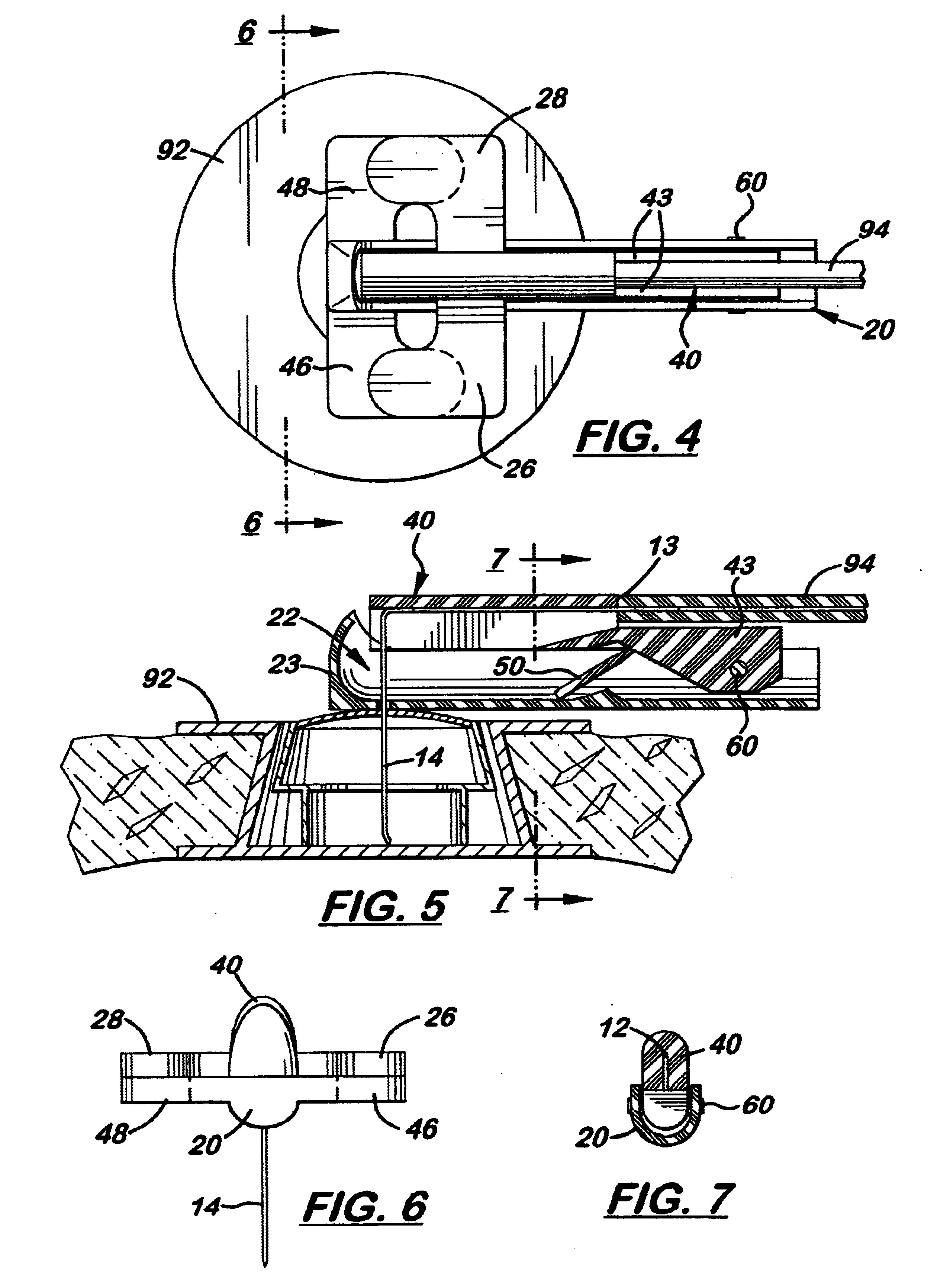
These and other objects of the present invention are met by a safety port needle assembly used to connect an IV line to an implanted port needle receiving port. The assembly includes an L-shaped port needle with an integrally attached horizontal leg member and a vertical leg member. The horizontal leg member is disposed inside an elongated needle arm that is pivotally attached at one end to an elongated main body. The vertical leg member is perpendicularly aligned and extends downward from the distal end of the needle arm. A channel is formed in the main body that enables the needle arm to nest longitudinally inside the main body. A bore is also formed in the main body that enables the vertical leg member to extend downward through the main body when the needle arm is longitudinally aligned with the main body. Located in front of the bore is a pocket space which receives the tip of the port needle when extended above the bore. Also, formed near the distal end of the main body is a pair of laterally extended wings that enable a healthcare worker to securely hold the main body over the implant port using his or her fingers.
Disposed between the needle arm and the main body is an upward rotation limiting means that prevents the needle arm from being rotated upward excessively so that the tip of the needle is exposed. In the preferred embodiment, the upward rotating limiting means is a beveled surface formed on the needle arm that presses against the main body and prevents the needle arm from pivoting upward beyond a desired angle. Also provided is an optional downward rotation limiting means that provides the needle arm from being accidentally rotated downward after being rotated upward to prevent punctures. Also attached to the distal end of the needle arm is an optional pair of laterally extended wings that enables the needle arm to be easily rotated by the healthcare worker.
During use, an IV tube is connected to the proximal end of the horizontal leg member that extends rearward from the proximal end of the needle arm. The tip of the vertical leg member is then inserted into the implant port so that the second pair of wings is positioned directly against the patient's skin surround the implant port. The needle assembly can then be used to deliver fluids to the implant port. When de-accessing the implant port, the healthcare worker places the fingers of one hand over the first pair of wings to stabilize the main body over the implant port. The healthcare worker then grasps the second pair of wings with the fingers of the opposite hand, and lifts upward. As the second pair of wings is lifted, the needle arm pivots upward over the main body. When the needle arm pivots a sufficient distance, as determined by the length of the vertical leg of the port needle and the relative angle of the beveled surface, the tip of the vertical leg member extends above the bore on the main body. As the needle arm is pivoted rearward, a rearward directed force is applied to the vertical leg member. When the distal end of the vertical leg member extends past the bore, the vertical leg member snaps forward so that it is perpendicularly aligned with the horizontal member. When the vertical leg member snaps forward, it is received by the pocket space formed on the main body to further protect against accidental punctures.

Problems solved by technology

VAPs are typically used in patients who need intermittent long-term I.V. therapy but can't use an external central venous catheter.
Because the nurse or I.V. therapist must stabilize the port between his or her fingers while the Huber needle is pushed or pulled from the port, accidental puncture sometimes occurs.
Also, because the old needle may be quickly deposited, placing the old needle into the opening of a Sharps container can lead to accidental skin punctures.

Method used


Image

  • Safety port needle assembly
  • Safety port needle assembly
  • Safety port needle assembly

Examples


Embodiment Construction

)

Disclosed herein is a safety port needle assembly, generally referenced as 10 in the accompanying Figures., used to connect an I.V. line 94 to an implanted port needle receiving port 92 attached to a patient 90. More specifically, the needle assembly 10 is designed to prevent accidental punctures in accessing and de-accessing an implant port 92.

The needle assembly 10 includes an L-shaped port needle 12 similar to a Huber needle with an integrally attached horizontal leg member 13 and a vertical leg member 14. The horizontal leg member 13 of the port needle 12 is longitudinally aligned and attached to a pivoting needle arm 40. The vertical leg member 14 extends downward perpendicular to the longitudinal axis of the needle arm 40. A channel 22 is formed along the entire length of the main body 20 that enables the needle arm 40 to rest partially inside the main body 20 when folded downward over the main body 20, as shown in FIGS. 3-5. A bore 24 is also formed in the main body 20 so th...


PUM


Abstract

A safety port needle assembly used to connect an IV line to an implanted port needle receiving port. The assembly includes an L-shaped port needle with an integrally attached horizontal leg member, a vertical leg member, an elongated, fixed main body and a pivotally attached needle arm. The horizontal leg member is longitudinally aligned and attached to the needle arm. The vertical leg member extends downward perpendicular to the longitudinal axis of the needle arm. A channel is formed in the main body that enables the needle arm to rest longitudinally against the main body. A bore is also formed in the main body so that the vertical leg member may extend downward through the main body. Formed near the distal end of the main body is a pair of laterally extended wings.

Description

1. Field of the InventionThe present invention relates generally to the field of body entering conduits, and, more particularly, to conduits having protective levers to prevent accidental punctures.2. Description of the Related ArtMedications are commonly administered by injection or continuous infusion into an implanted port, known as a vascular access port (VAP). VAPs are typically used in patients who need intermittent long-term I.V. therapy but can't use an external central venous catheter.In order to administer medication through the port, access through the port must be obtained by carefully inserting a non-coring bent needle known as a Huber needle into the silicone injection septum located in the port. During the procedure, known as "accessing the port", the nurse or I.V. therapist is required to palpate and stabilize the port under the skin between his or her thumb and forefinger. While holding the Huber needle like a dart, at a 90-degree angle over the septum, the needle i...

Claims


Application Information

Patent Timeline
Patent Type & Authority Patents(United States)
IPC IPC(8): A61M5/158A61M5/14A61M1/00
CPCA61M5/158A61M5/3275A61M39/0247A61M2005/1581A61M2005/3249
Inventor OKAZAKI, ELIZABETHOKAZAKI, RICHARDOKAZAKI, PAUL
Owner LRP L L C
Learn More