Eureka AIR delivers breakthrough ideas for toughest innovation challenges, trusted by R&D personnel around the world.

Differential amplifier with gain substantially independent of temperature

a technology of gain and amplifier, applied in amplifiers, amplifiers with semiconductor devices/discharge tubes, electrical devices, etc., can solve problems such as low output voltage of common mode, large chip area for integration onto a single chip, and limited gain by resistor ratio

Inactive Publication Date: 2004-03-30
UNIVERSITE CATHOLIQUE DE LOUVAIN
View PDF9 Cites 13 Cited by
  • Summary
  • Abstract
  • Description
  • Claims
  • Application Information

AI Technical Summary

Benefits of technology

A further object is to provide a differential amplifier with a simpler circuit design.
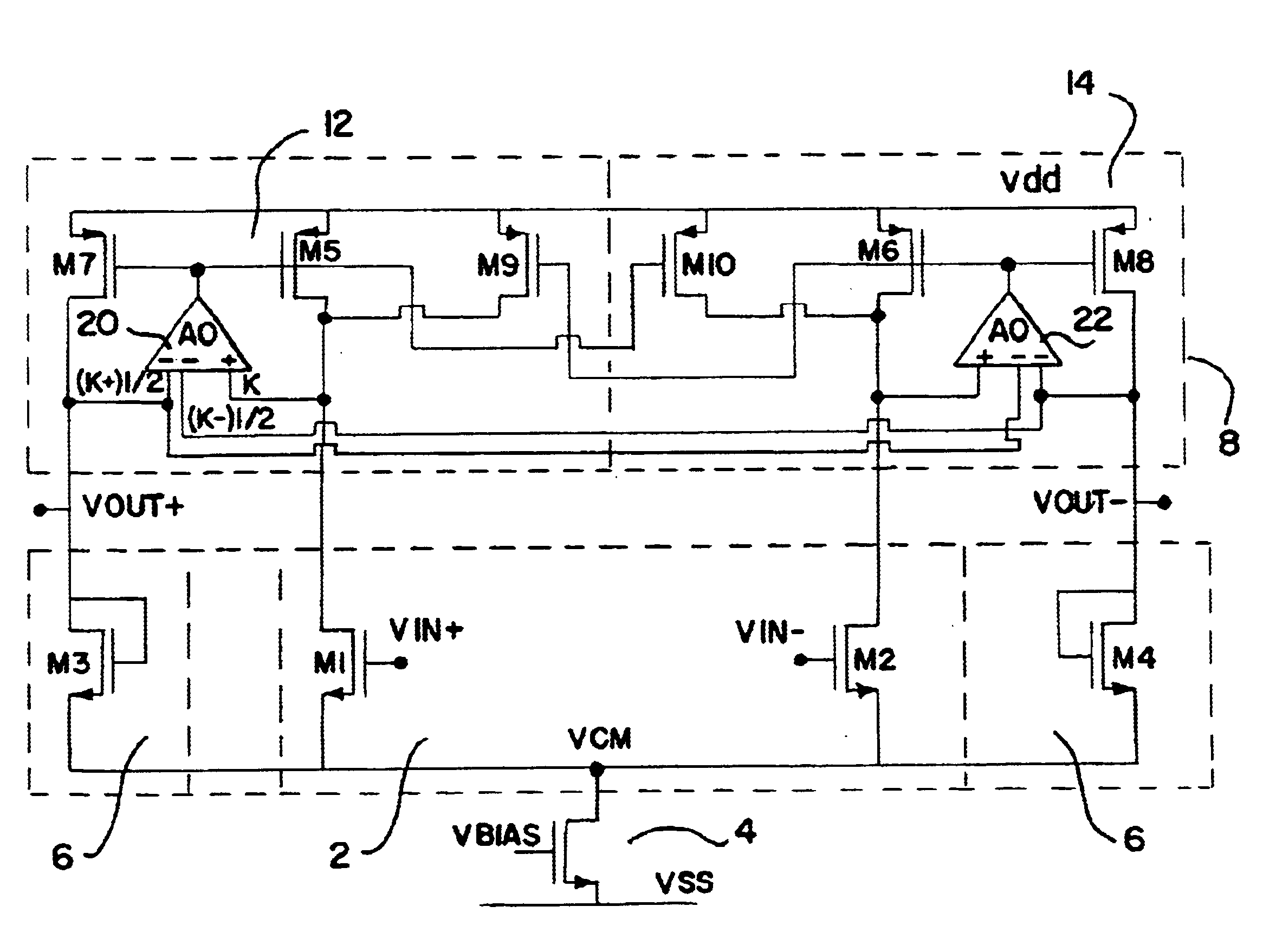
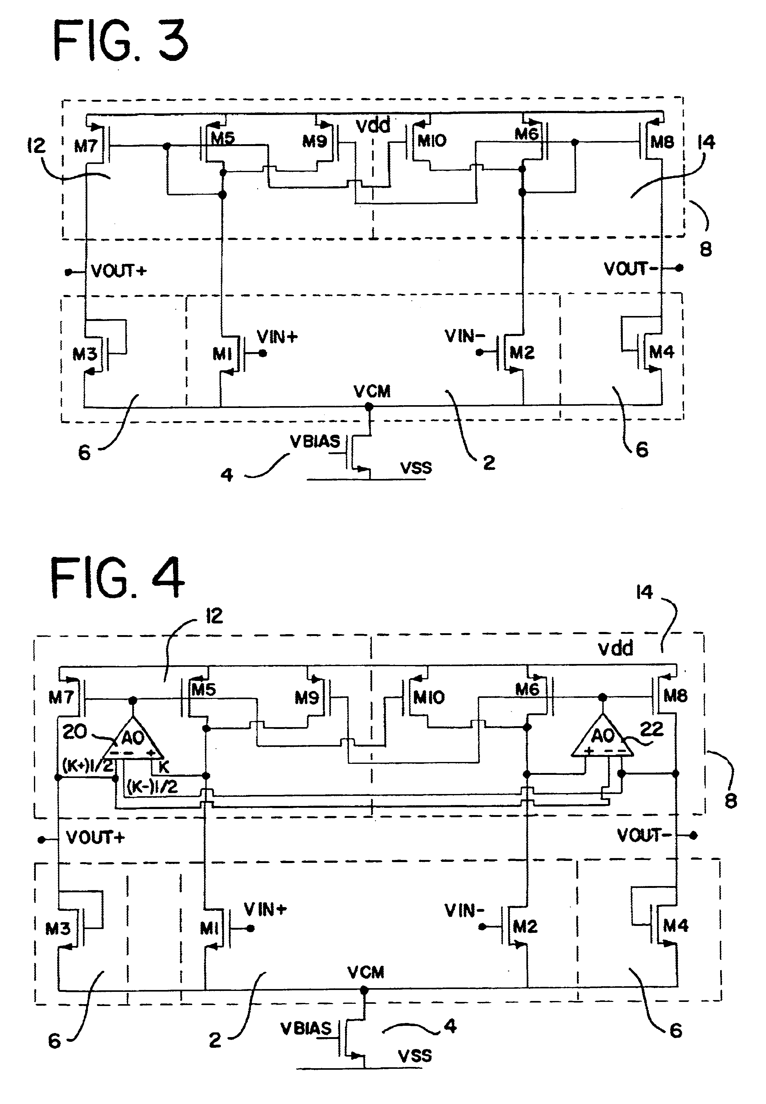
The differential amplifier may further comprise an active load circuit, the active load circuit linking the input branch to the output branch and having a larger differential gain than common mode gain. The active load circuit may comprise two current mirror circuits linking the input branch to the output branch, wherein the current mirror circuits each have a differential gain different from its common mode gain. The active load circuits are designed to provide the same current densities in the transistors of the input and output branches. This improves the temperature response of the amplifier. The amplifier is preferably implemented using active devices of the same type and manufacture, e.g. transistors and that by matching these transistors the differential gain is constant to within 1 dB, more preferably to within 0.5 dB, and most preferably to within 0.2 dB over a temperature over a range of at least 100.degree. C., more preferably at least 150.degree. C. nd most preferably over 200.degree. C.
The amplifier described above is preferably used as a preamplifier. The amplifier may be constructed in a variety of technologies, e.g. MOS field effect transistors, bipolar transistors, SOI. One particular advantage is that it does not require passive components so that it may be integrated easily and compactly onto a single chip.

Problems solved by technology

There are several problems with this known device.
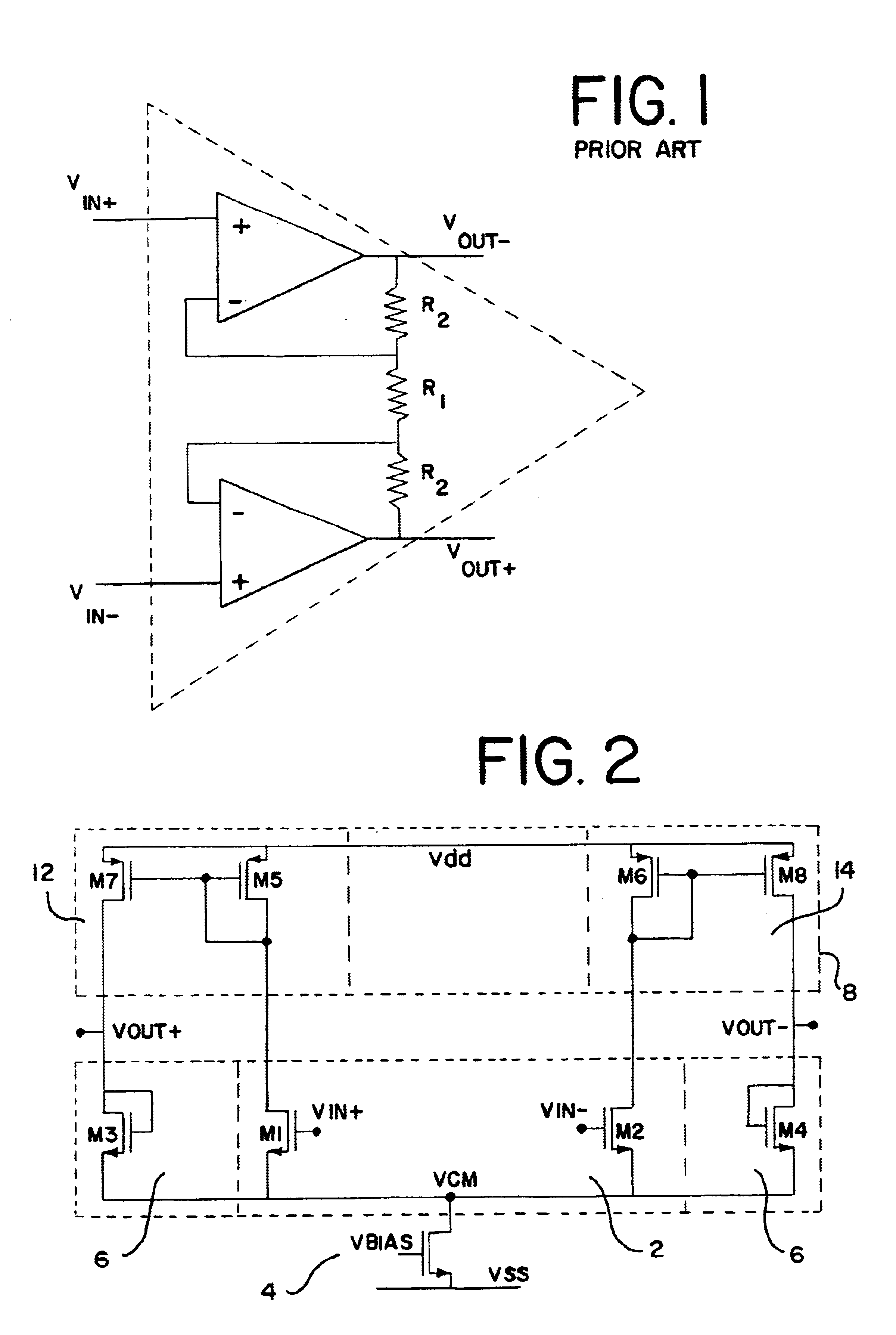
First of all the gain is limited by the resistor ratio obtainable.
Secondly, integration onto a single chip requires a lot of chip area for the resistors and amplifiers with Miller capacitors and current-consuming output stages to drive the resistors.
If this is not done, the common mode output voltage may be too low, pushing the input transistors into the linear region.

Method used


Image

  • Differential amplifier with gain substantially independent of temperature
  • Differential amplifier with gain substantially independent of temperature
  • Differential amplifier with gain substantially independent of temperature

Examples


first embodiment

the present invention is shown schematically in FIG. 2. It is a fully differential amplifier and comprises an input branch 2 comprising a differential and common mode input of, for instance, a matched pair of transistors M1 and M2 of a first conductivity type, e.g. NMOS, with one of their main current electrodes connected together, e.g. their sources. The output branch 6 comprises a second differential and common mode device comprising two matched transistors M3 and M4 having the first conductivity type, e.g. NMOS, and being diode connected, for example, the gate and drain electrodes connected together. The one main current electrodes of transistors M3 and M4 are connected to the one main current electrodes of the input pair M1 and M2 so that these all lie on the same potential. This one common electrode, e.g. source, is connected to a voltage or current source 4 depending on the application and the required performance. The one common electrode for M1 to M4 avoids the need of a sep...


PUM


Abstract

A differential amplifier is described comprising an input branch for receiving differential and common mode input signal components; an output branch providing differential and common mode output signal components; and the differential amplifier being adapted to set a relationship between the magnitude of the common mode output signal component level of the amplifier with respect to the magnitude of the common mode input signal component level to the input stage so that the common mode output signal component level intrinsically follows the common mode input signal component level as a common mode follower without using feedback control of the common mode output signal component. Also an asymmetrical amplifier is described which may be advantageously used as a component of the differential amplifier.

Description

The present invention relates to a differential amplifier, particularly to an instrumentation preamplifier or sensor differential amplifier. Such amplifiers preferably have constant gain over a wide temperature range. The present invention also relates to an asymmetrical differential amplifier with differing gains on its two inputs.TECHNICAL BACKGROUNDIn analog circuitry, signals are often represented by differential signals, e.g. voltages or currents. A differential signal may be described by a common mode component and a differential component. The common mode component may be looked upon as the average of two signals whereas the differential component is the difference between the same signals. Preferably, a differential amplifier has a high immunity to common mode changes or noise (high common mode rejection) and is therefore often preferred compared to a single end amplifier. Different applications place different requirements on a differential amplifier, for instance very prec...

Claims


Application Information

Patent Timeline
Patent Type & Authority Patents(United States)
IPC IPC(8): H03F3/45
CPCH03F3/45183H03F3/4565H03F3/45659H03F2203/45644H03F2203/45658H03F2203/45682
Inventor DESSARD, VINCENTFLANDRE, DENIS
Owner UNIVERSITE CATHOLIQUE DE LOUVAIN
Why Eureka
Eureka Blog
Learn More