Eureka AIR delivers breakthrough ideas for toughest innovation challenges, trusted by R&D personnel around the world.

System and method for braking an electric drive vehicle on a low Mu surface

a technology of electric drive vehicle and mu surface, which is applied in the direction of braking system, braking components, electric devices, etc., can solve the problem of certain times to invoke regenerative braking

Inactive Publication Date: 2004-03-23
FORD GLOBAL TECH LLC
View PDF23 Cites 127 Cited by
  • Summary
  • Abstract
  • Description
  • Claims
  • Application Information

AI Technical Summary

Problems solved by technology

While some energy recovery is made possible by regenerative braking, it is inappropriate at certain times to invoke regenerative braking.

Method used


Image

  • System and method for braking an electric drive vehicle on a low Mu surface
  • System and method for braking an electric drive vehicle on a low Mu surface
  • System and method for braking an electric drive vehicle on a low Mu surface

Examples


Embodiment Construction

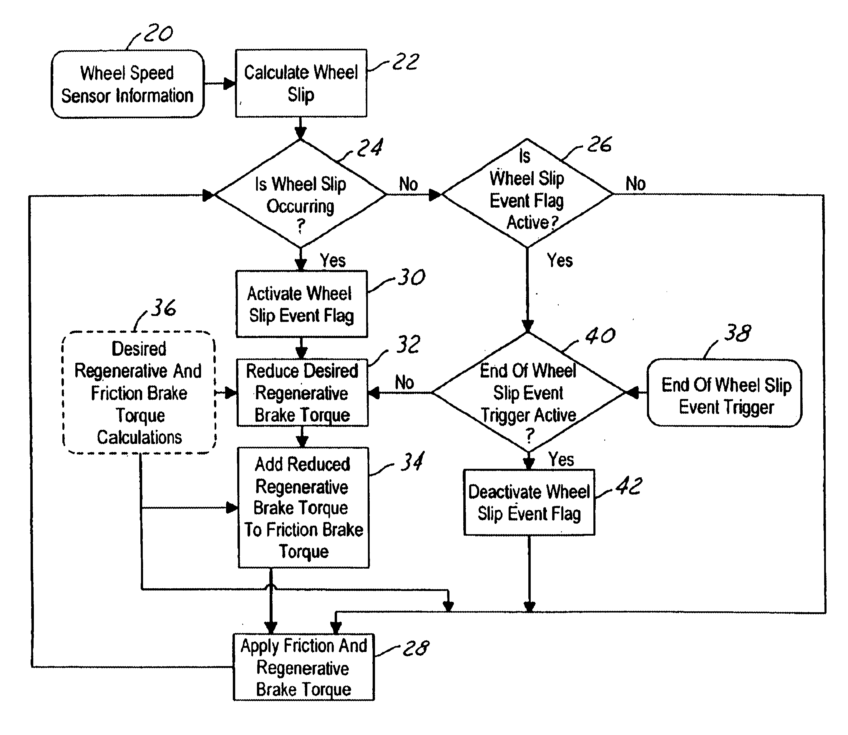
A representative torque controller for the powerplant of an electric drive vehicle includes a powertrain control module (PCM) and a brake control unit (BCU). It should be appreciated that the descriptive term control module, or control unit, is used in a generic sense, and not in a limiting sense, to designate an electronic unit that comprises an assembly that comprises various electronic components, including a processor, for processing various data inputs and delivering various data outputs to perform selected functions in the manner herein described. The vehicle powerplant comprises a rotary electric machine that can operate either as an electric motor for propelling the vehicle or as an electric generator for braking the vehicle. The vehicle also includes a service brake system for braking the vehicle via the application of friction brakes.

The friction brakes may be applied in any suitable way. For example, the driver may depress a brake pedal to actuate the brakes via electric-...


PUM


Abstract

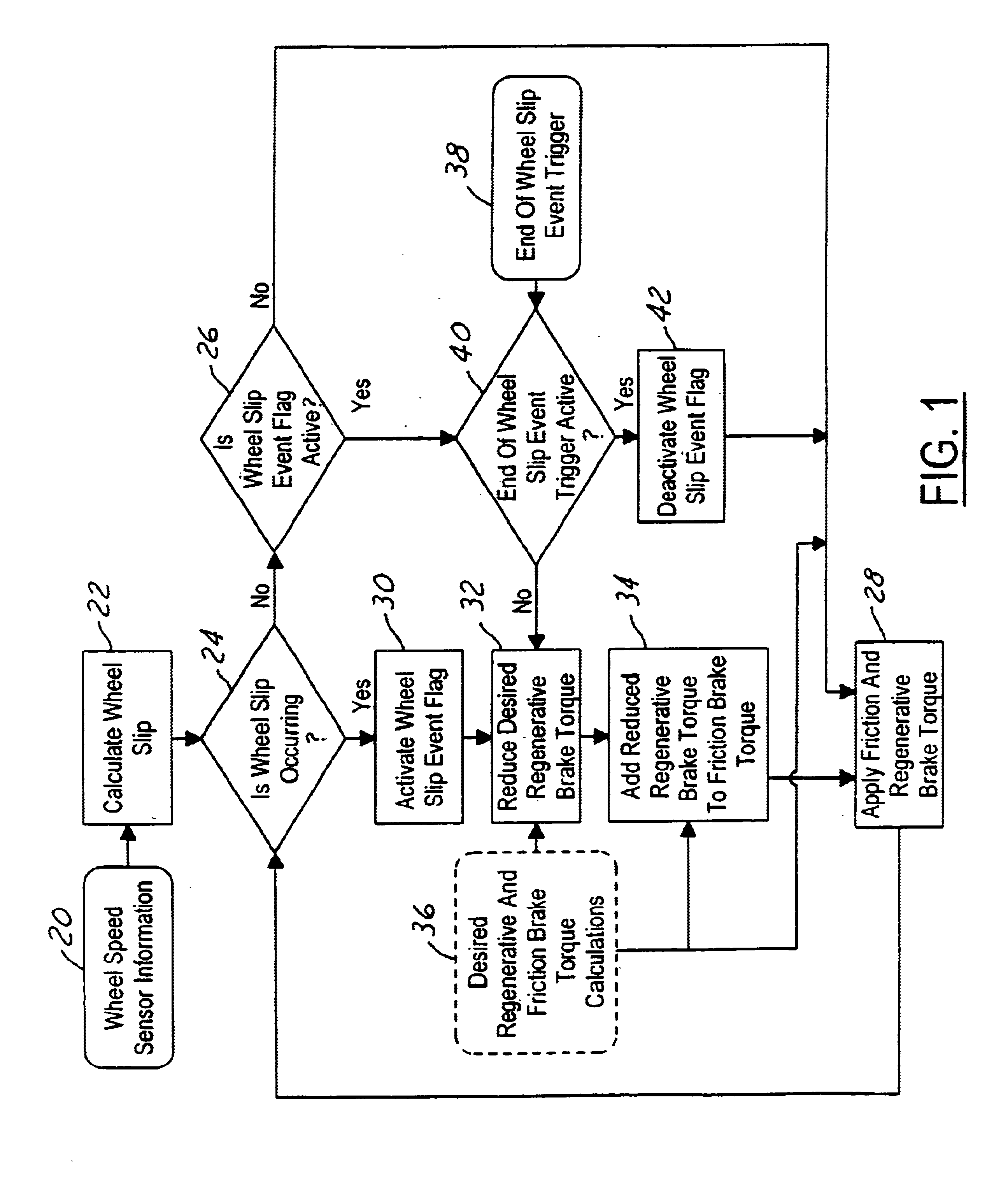
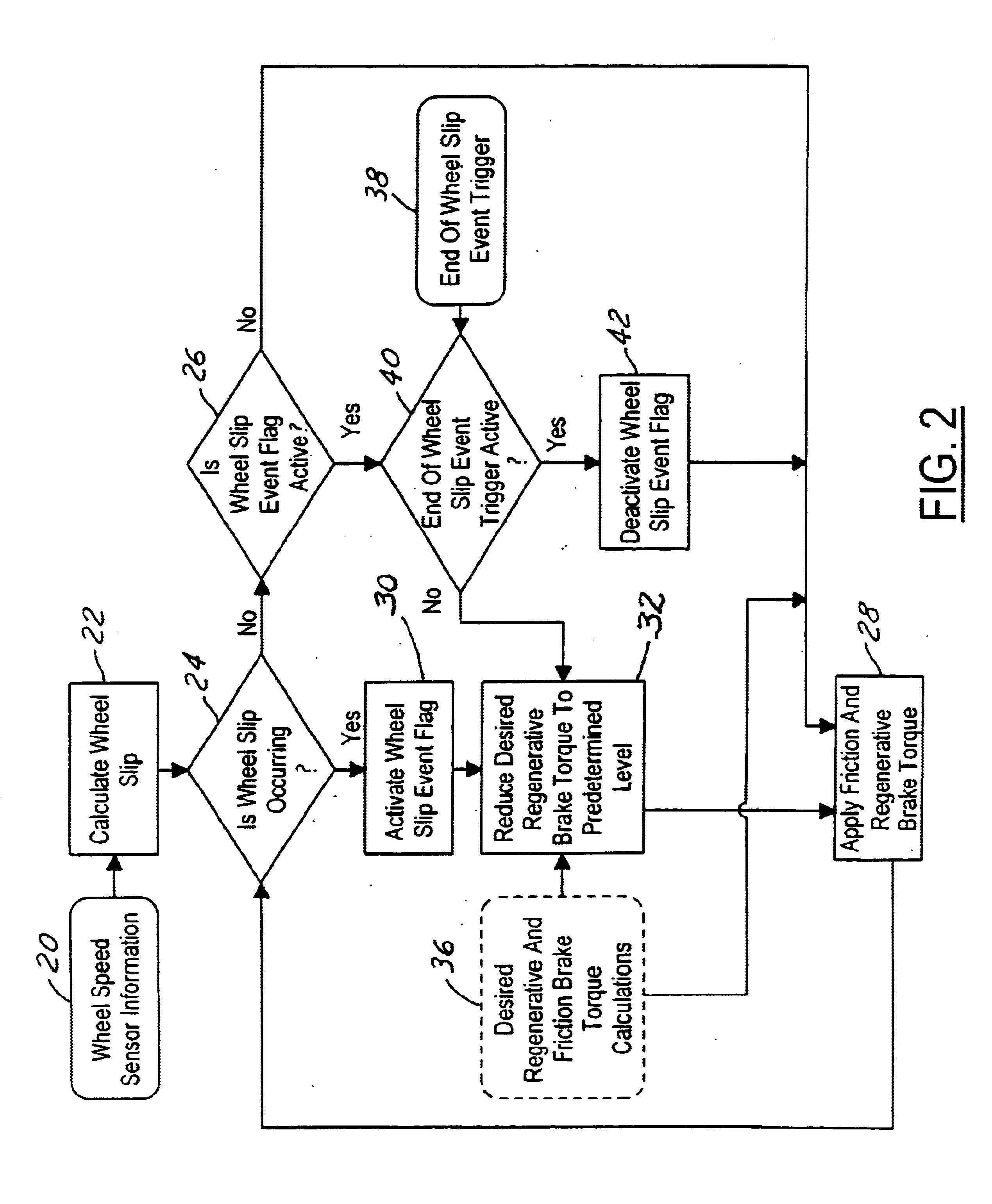
Strategies other than immediate elimination of regenerative braking (FIG. 2) are invoked when an incipient wheel lock-up is detected, the ABS becomes active, and / or incipient wheel slip is detected. The strategies include: reducing the regenerative braking torque as a function of the coefficient of friction of a surface on which the vehicle is traveling (FIG. 3); and adjusting regenerative braking in relation to the rate at which wheel slip is changing (FIG. 4). Some of the strategies may be applied on an individual wheel basis (FIG. 5), and some of the strategies may be applied in conjunction with operating friction brakes of the vehicle to apply at least some of the reduction in regenerative braking torque as friction brake torque (FIG. 1).

Description

1. Field of the InventionThis invention relates to braking systems of electric drive vehicles, and in particular to strategies for modifying regenerative braking that might otherwise potentially affect vehicle handling when the brake pedal is depressed while the vehicle is traveling on a low Mu surface and / or while an anti-lock brake system (ABS) is actively controlling the application of friction brakes at the vehicle wheels.2. Background InformationThe powertrain of an electric drive vehicle comprises a rotary electric machine whose operation may be under the control of a powertrain control module (PCM), a name that is sometimes given to an electronic module that processes certain data to control various aspects of powertrain operation. Sometimes the electric machine operates as a motor that makes a positive torque contribution to powertrain torque. At other times the electric machine operates as a generator that makes a negative torque contribution to powertrain torque. Positive ...

Claims


Application Information

Patent Timeline
IPC IPC(8): B60L3/10B60L15/20B60T8/1763B60T8/17B60L7/10
CPCB60L3/102B60L7/10B60L15/2009B60T8/17636B60T2270/602Y02T10/7275Y02T10/64Y02T10/72
Inventor CROMBEZ, DALE SCOTTPATE, STEVEN OTIS
Owner FORD GLOBAL TECH LLC
Why Eureka
Eureka Blog
Learn More