
Survivability and mission flexibility enhancements for reconnaissance aircraft

a technology of mission flexibility and aircraft, which is applied in the direction of cosmonautic vehicles, firework flares/torches, aircraft display rockets, etc., can solve the problems of difficult visual detection, low observable aircraft operating at night, and large sensor pods, so as to reduce the signature of the parent aircraft, less stealth, and less expensive

Inactive Publication Date: 2004-03-16
ADVANCED AEROSPACE TECH
View PDF12 Cites 35 Cited by
  • Summary
  • Abstract
  • Description
  • Claims
  • Application Information

AI Technical Summary

Benefits of technology

Although the current invention can place sensors in a fixed location near the ground and at a low grazing angle relative to an object of interest like the ROSS system the primary purpose of the current invention is to turn cloud cover from a disadvantage for aerial reconnaissance into an advantage by hiding the aircraft behind the clouds and placing the sensors and targeting equipment below the clouds.
Also the ROSS system sensor pod was envisioned as operating near the ground where targets of interest are located and didn't envision the aircraft operating in or above the clouds. As a result there was no consideration that the cable would be in the clouds and thus would need an anti-ice capability. Also the ROSS system patent also never envisioned sensors and / or methods for making sure the aircraft was hidden and thus protected by the clouds from ground based visual and infrared guided weapons. Also no sensors and / or methods were envisioned for keeping the sensor pod below the clouds and / or not farther below the clouds than necessary to perform their reconnaissance function. Placing the sensor pod farther below the clouds than necessary especially when the aircraft is flying in a straight line to cover more ground significantly increases the cable drag and requires more cable length than necessary. In one embodiment of the current invention cable drag is also reduced by having a power source onboard the sensor pod to eliminate the need to transmit power down the cable and allow a smaller diameter cable.
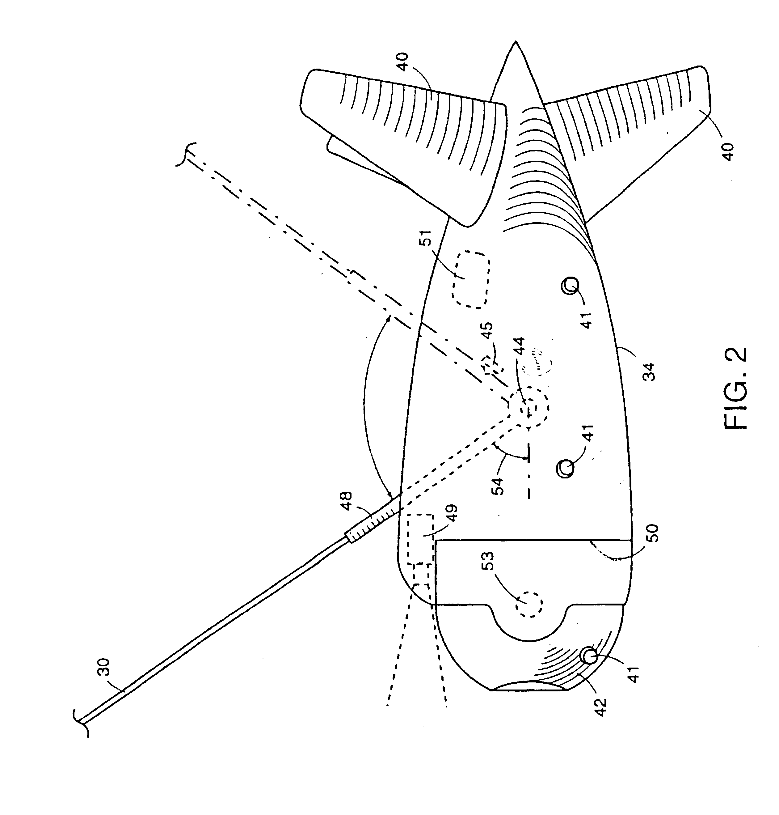
The ROSS system didn't address minimizing cable and sensor pod drag since the sensor pod was intended to be used while stationary in the air near the ground observing targets whereas the current invention is intended to be useable by a higher flying aircraft and both while stationary but more often while translating to cover more ground. The ROSS sensor pod was made aerodynamically draggy on purpose to help make the cable more stable during recovery. For the current invention the sensor pod is preferably streamlined to minimize the cable sweep back angle and maximize the vertical separation between the aircraft and the sensor pod in translational flight with a fixed length of cable. The sensor pod also wants to be streamlined because draggy shapes, such as spheres, towed through the air tend to be unstable and jump around resulting in a poor sensor platform. The current invention also preferably uses tail fins on the sensor pod to stabilize it using the airstream and a gimbaled sensor system so that the operator can point the sensors in the desired direction relative to the pod.
Various preferred embodiments of my invention are disclosed herein. Some of them locate laser designators closer and in clearer view of targets than the parent aircraft. Some reduce the signature of the parent aircraft by remotely locating the sensors and / or targeting equipment. Some allow less expensive, less stealthy sensors / targeting equipment without drawing enemy fire to the parent vehicle. Some use the aircraft's sensors / targeting equipment as a decoy for the parent vehicle. Some provide a streamlined sensor pod with a roll-theta or azimuth-elevation gimbaling system for the sensors. Some minimize the drag and length of the tow cable required in order to place sensors in view of ground targets yet hide the aircraft behind cloud cover.
In accordance with some of the preferred methods of the present invention, a zig-zag flying pattern for the parent aircraft is provided so as to reduce cable drag, and achieve greater vertical separation between the parent aircraft and the sensor pod without excessive vertical oscillations of the sensor pod. In some of the methods, the aircraft is operated to best hide behind or in clouds and a way is provided to minimize the vertical separation between the aircraft and pod and still get the full protection desired.

Problems solved by technology

The sensor pod is much smaller and harder to visually detect than the rest of the airframe and contains only what is necessary to perform its task without a large infrared source like the aircraft's engine.
The downing of a stealth fighter in Kosovo has highlighted the fact that even low observable aircraft operating at night are still vulnerable when they drop down below the cloud cover to try to detect targets.
However the experience in Kosovo has caused the Air Force to initiate plans to retrofit laser designators onto all their predator UAVs yet no one during or since Kosovo considered adding a laser designator to the sensor pod of a ROSS system.

Method used


Image

  • Survivability and mission flexibility enhancements for reconnaissance aircraft
  • Survivability and mission flexibility enhancements for reconnaissance aircraft
  • Survivability and mission flexibility enhancements for reconnaissance aircraft

Examples


Embodiment Construction

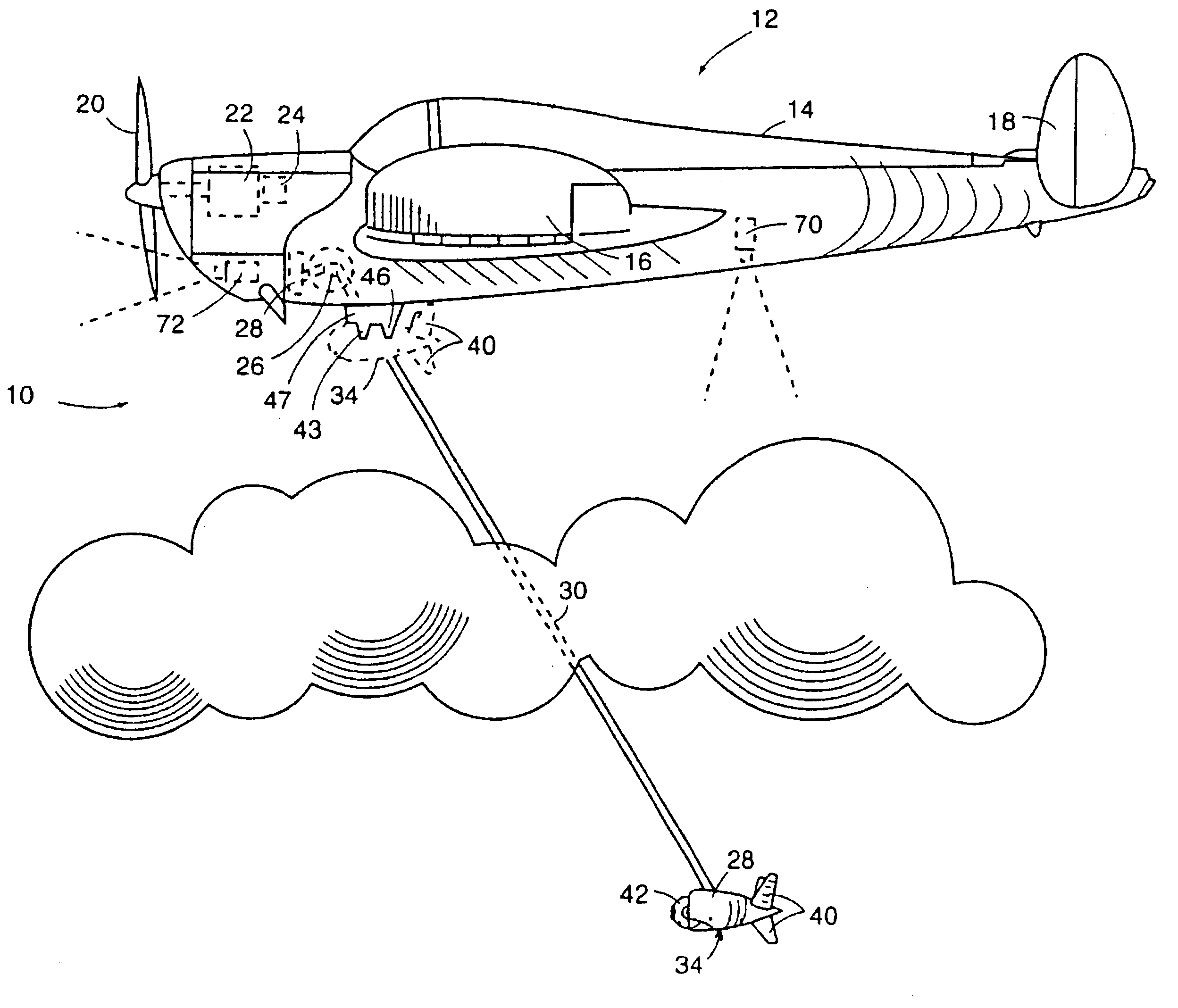
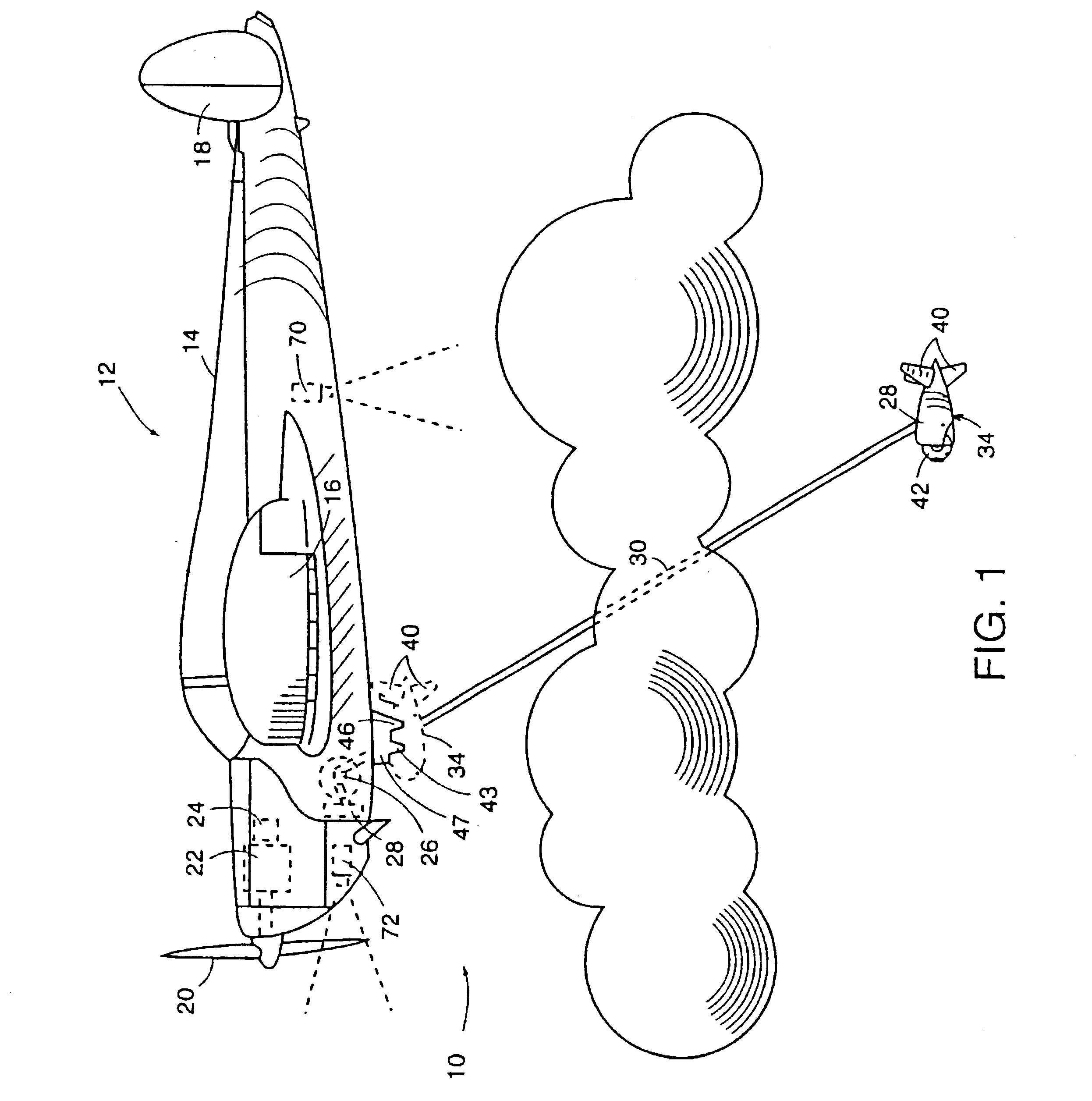
Referring now by reference numerals to the drawings and first to FIG. 1, the aircraft system is generally indicated by 10 and consists of an aircraft 12 and an extendable sensor / targeting pod 34 shown in its extended position in solid lines and in its retracted position in dashed lines. The aircraft 12 includes a fuselage 14, wings 16, horizontal and vertical tail 18, propeller 20, engine 22, generator 24, winch 26, tow line 30 and data links 28. The pod 34 has stabilizing fins 40 and contains a roll-theta sensor and laser designator gimbaling system 42 as is well known in the art and similar to systems such as used on the Lockheed Martin AAS-38B FLIR pod. Power for the pod 34 is provided by airframe mounted generator 24 through copper lines (not shown) in tow line 30 as is well known in the art for towed decoy systems. It is also understood of course that the pod could contain its own battery or own generator. In fact for very long fiber optic cables and very small sensors an onboa...


PUM


Abstract

A pod (34) containing sensors and / or targeting systems such as laser designators or range finders are hung on a cable (30) below an aircraft (12). The line (30) can be reeled in or out similar to towed decoys. This allows the aircraft (12) to operate above or in the cloud cover while the sensors / targeting equipment (34) are operating below the cloud cover to find the enemy forces.

Description

The present invention relates to heavier than air or lighter than air aircraft where it is desirable for the air vehicle to operate at a higher altitude to stay out of the most effective range of light arms fire and / or to hide behind the natural cloud cover, smoke or atmospheric haze while still being able to get its sensors and targeting systems closer to the ground and beneath the cloud cover, atmospheric haze, fog, smoke, etc. Sensors are also more difficult to make stealthy than other airframe components. This invention also relates to aircraft that want to reduce their signature, draw enemy fire away from the mother aircraft, and / or want to use less expensive non-stealthy sensors without drawing enemy fire to the parent aircraft itself.The conflict in Kosovo has highlighted a shortfall in the ability to find camouflaged enemy ground forces under cloud cover, haze or smoke. Both manned and unmanned aerial vehicles (UAVs) must drop below the cloud layer to find enemy forces and / o...

Claims


Application Information

Patent Timeline
Patent Type & Authority Patents(United States)
IPC IPC(8): B64D3/00B64D47/00B64D7/00B64D47/08F41G3/02
CPCB64D3/02B64D7/00B64D47/08F41G3/02
Inventor MCDONNELL, WILLIAM R.
Owner ADVANCED AEROSPACE TECH
Learn More