
Apparatus and method for thermal desalination based on pressurized formation and evaporation of droplets

a technology of desalination apparatus and droplet, which is applied in the direction of boiling apparatus, solid separation, different sedimentation, etc., can solve the problems of low efficiency, 35 gallons of distilled water, and the method produces desalinized products at only about 35% efficiency

Inactive Publication Date: 2004-03-02
AQUASONICS RSE INC
View PDF23 Cites 70 Cited by
  • Summary
  • Abstract
  • Description
  • Claims
  • Application Information

AI Technical Summary

Problems solved by technology

The method produces desalinized product at only about 35% efficiency, meaning that only 35 gallons of distilled water results from every 100 gallons of input seawater.
The multiple stages, pressures, vacuums, and low efficiency are economical barriers to wider use of the technology.
The practicality, and popularity, of reverse osmosis membrane systems are hindered by the capital costs of RO membranes, as well as expense associated with RO membrane maintenance.
Although such methods can separate salt (sodium chloride, as well as other chemical salts such as potassium chloride) from seawater, large production rates have not been achieved or predicted at economical advantages.
The prior apparatuses do not describe economical methods, and they employ methods of condensing that are economically unattractive, being costly to scale up to commercial levels of production.
Furthermore, and importantly, creating droplets using compressed air requires excessive amounts of energy relative to other known methods of desalination.
To the applicants' knowledge, however, none of the known methods or devices utilize fogging or misting, together with both waste heat over a range of temperatures and water collection upon cold-water condensers, to produce desalination under conditions that are economically attractive for commercial production of large quantities of fresh water from seawater.

Method used


Image

  • Apparatus and method for thermal desalination based on pressurized formation and evaporation of droplets
  • Apparatus and method for thermal desalination based on pressurized formation and evaporation of droplets
  • Apparatus and method for thermal desalination based on pressurized formation and evaporation of droplets

Examples


example

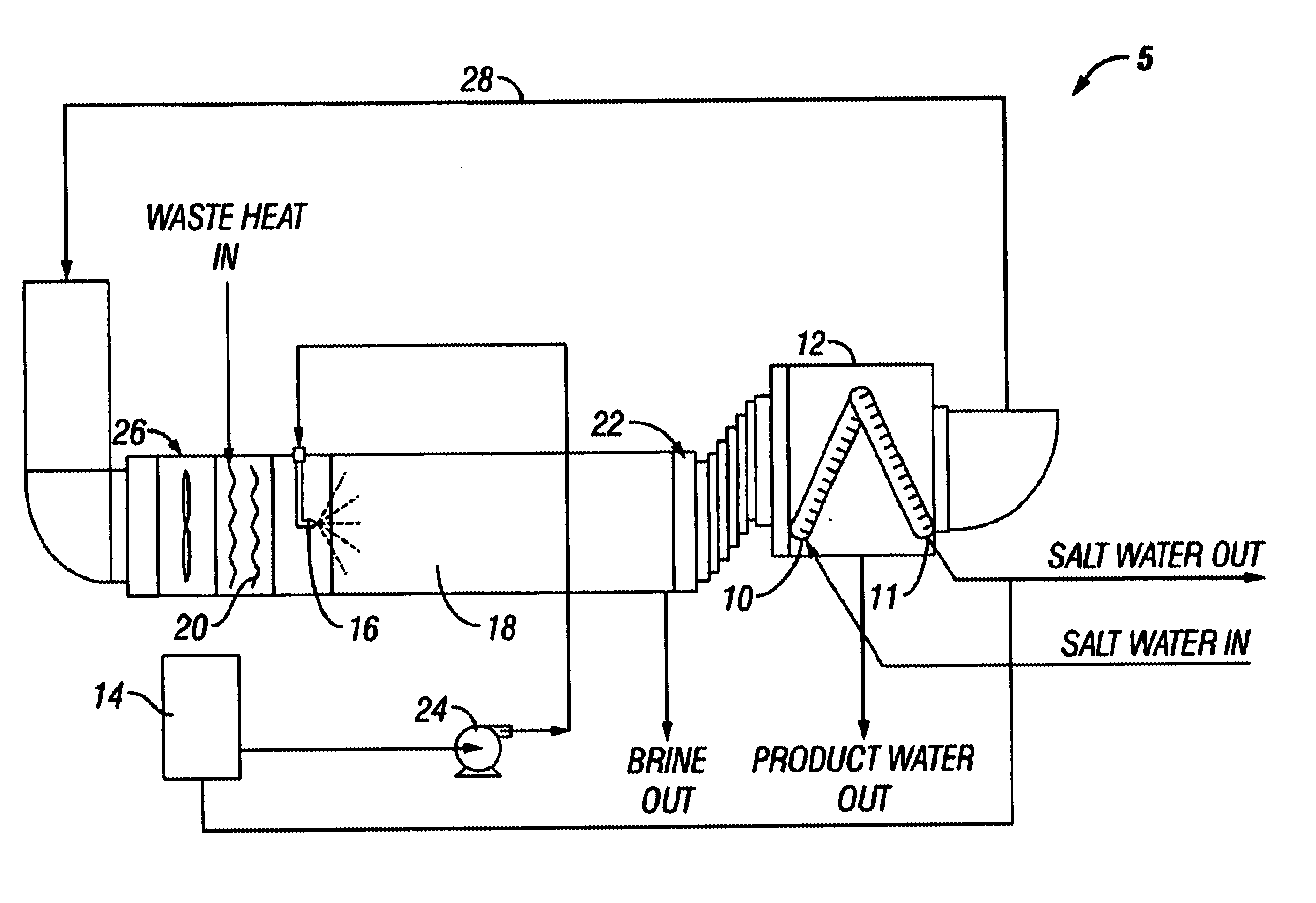
It is assumed that the available waste-heat source provides for heated air at 250F. Requiring that the temperature of the air entering the heat exchanger, as well as the air exiting the condenser, is 100 F at 100%. relative humidity (RH), the enthalpy of the entering air accordingly is 62.8 BTU per pound of air. (Values used for enthalpy and humidity are taken from a "Humidity Chart for Air and Water" in "Chemical Engineering Reference Manual" 4th edition, by Randall Robinson, PE. The chart is based upon thermodynamic data for air and water, the latter from the Keneen and Keyes steam tables published in 1936.)

The heated air temperature is 250 F and the heated air enthalpy is 105 BTU per pound of air. The evaporation temperature, i.e., the temperature of the water vapor and air entering the condenser, is 123 F, at 90% RH.

The difference in humidity of the air entering the condenser (90%RH at 123 F) and exiting the condenser (100% RH at 100 F) is:

0.080-0.043=0.037 lbs of water per lb o...


PUM

PropertyMeasurementUnit
Pressureaaaaaaaaaa
Pressureaaaaaaaaaa
Pressureaaaaaaaaaa

Abstract

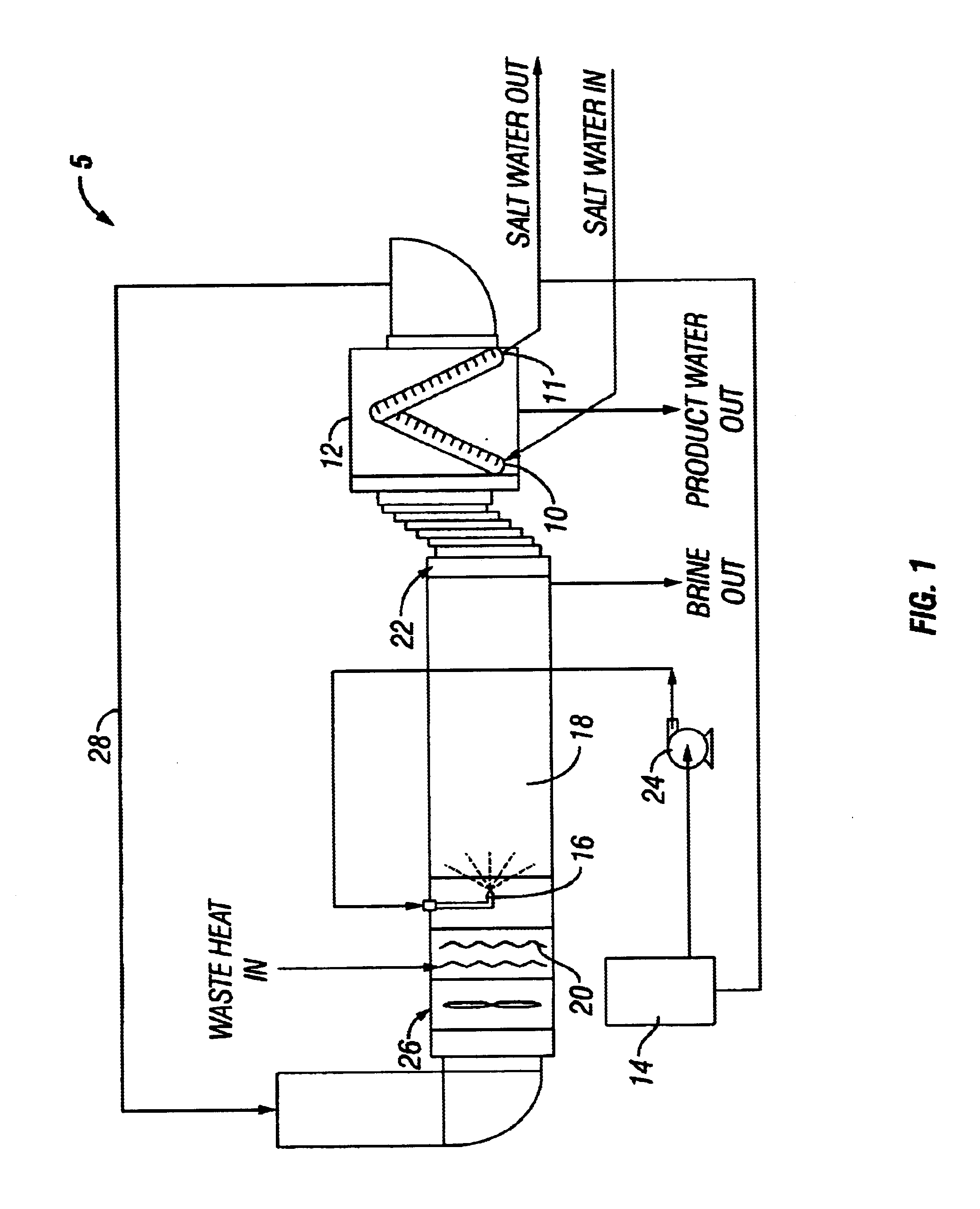
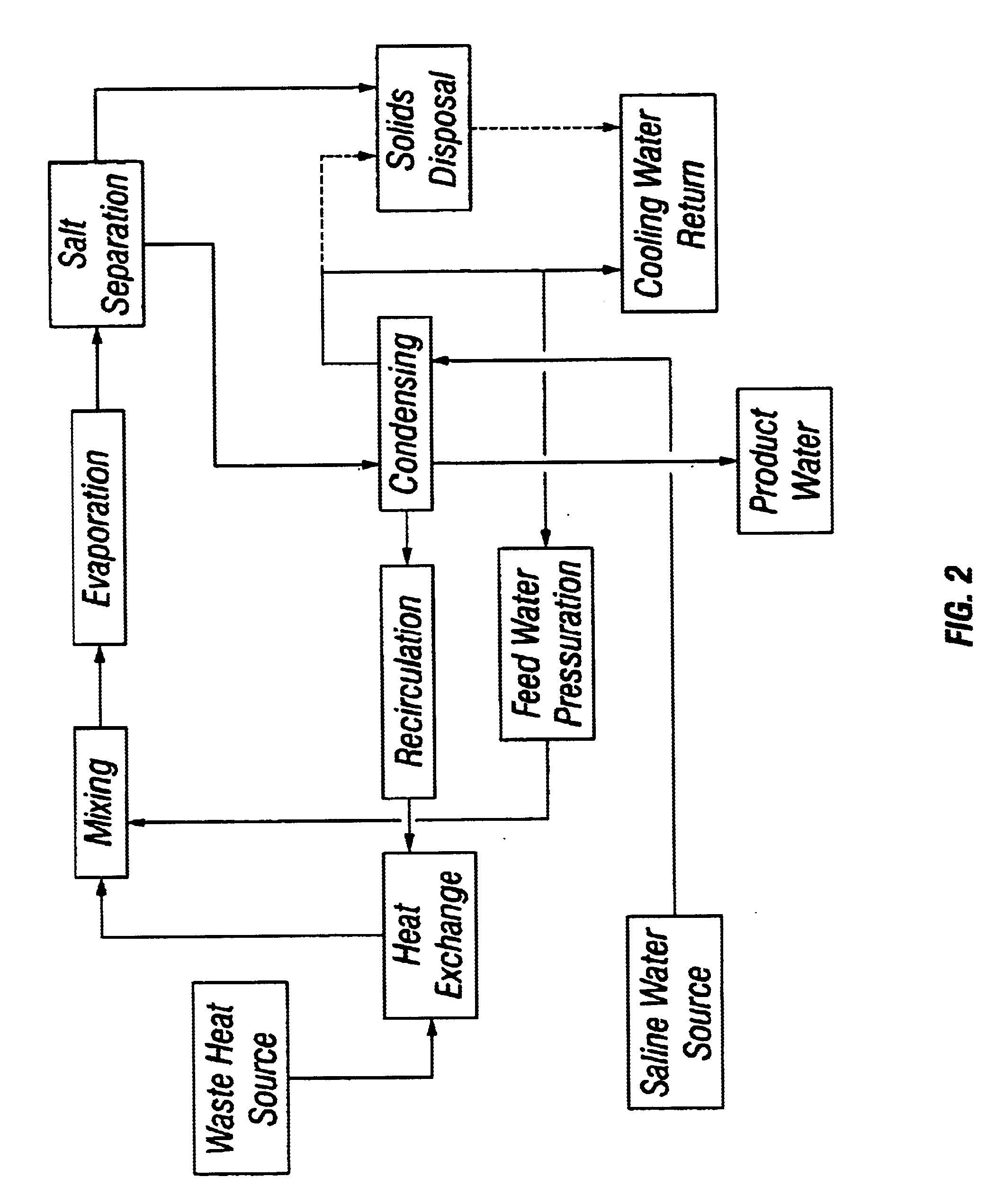
A method for removing dissolved solids, particularly salts, from water. An apparatus for performing the inventive method is disclosed. The aqueous solution to be treated, for example sea water, is atomized using special non-pneumatic nozzles, and sprayed into an evaporation chamber through which air, heated by waste heat, is blown. The micro-droplets undergo rapid evaporation in the chamber, resulting in the separation of the salt solids from the vapor phase of the water. The mixture of suspended solids and water vapor is filtered to remove and collect the salts, and the water vapor is condensed to collect the salt-free water.

Description

1. Field of the Invention (Technical Field)The present invention relates to methods for separating solids from liquids, particularly to a method of desalinating water.2. Background ArtConventional methods of thermal desalination typically use distillation of seawater through a process of evaporating seawater and condensing the resulting water vapor, producing "salt-free" water. The most frequently encountered method of thermal desalination, commonly called "multi-stage flash," requires high temperatures, and operates from ambient (or elevated) pressures in the first stage to a high vacuum in the last stage, to effect temperature and pressure gradients for distillation and efficient heat utilization. The method produces desalinized product at only about 35% efficiency, meaning that only 35 gallons of distilled water results from every 100 gallons of input seawater. The multiple stages, pressures, vacuums, and low efficiency are economical barriers to wider use of the technology.Other...

Claims


Application Information

Patent Timeline
IPC IPC(8): B01D1/16B01D1/18C02F1/04B01D5/00C02F1/08
CPCB01D1/18Y10S203/18Y10S203/11Y10S203/08Y02A20/124
Inventor HARTMAN, WILLIAM FRANCISKEPLEY, LARRY JOEFOX, JERRY VAN
Owner AQUASONICS RSE INC
Learn More