
Method for determining the permeability of a magnetic material by coaxial line perturbation

a magnetic material and coaxial line technology, applied in the direction of magnetic property measurement, measurement devices, instruments, etc., can solve the problems of complex numeric calculations, inability to directly characterize thin metallic layers and particularly thin ferromagnetic layers using this method, and inability to measure the permeability of thin ferromagnetic layers

Inactive Publication Date: 2004-01-13
COMMISSARIAT A LENERGIE ATOMIQUE ET AUX ENERGIES ALTERNATIVES
View PDF5 Cites 9 Cited by
  • Summary
  • Abstract
  • Description
  • Claims
  • Application Information

AI Technical Summary

Problems solved by technology

Furthermore, thin metallic layers and particularly thin ferromagnetic layers cannot be directly characterized using this method.
Variants have been developed using other types of guides, but they cannot be used to measure the permeability of thin ferromagnetic layers for the same reasons.
These samples only partially fill the guide, since sample dimensions are unacceptable (between 350-500 MHz, the dimensions are 53.4 by 27.9 cm).
But these methods lead to very complex numeric calculations [3] compared with the solution of the Nicholson and Weir equations.
1.degree.) the turn must be calibrated using the measurement of a known sample; however, there is no standard hyper frequency permeability, and no simple means of relation to a primary standard;
2.degree.) Apart from the limitation of its frequency band, a demagnetizing field is introduced by the parallelepiped shape of the sample [4]; since the dimension of the sample is limited in the direction parallel to the hyper-frequency magnetic excitation, poles are created at the ends which modifies the permeability of the sample compared with a larger sample. This effect gets weaker as the ratio between the dimension parallel to the excitation and the thickness increases.
The size limitation of the turns is related to their high frequency nature, and therefore it is not possible to increase the dimensions without reducing the accessible frequency band.
Therefore, it is very penalizing to be obliged to restrict measurements to short samples, as is the case for measurement in turns.
However, this method has disadvantages.
Methods of making thin layers and wires are rarely compatible with the production of a few tens of cubic millimeters of material.
Even if is possible to acquire the right quantity of material, it is still difficult to be sure about the uniformity of the properties of the rest of the material used to make the sample.
However, it is known that the risk of observing magnetostrictive effects that affect material properties increases as the stress increases.
The fact that the curvature varies considerably between the inside diameter and the outside diameter of the line makes any attempt at correcting or taking account of this effect illusory.
Finally, the last disadvantage of the measurement of a wound torus is that preparation of the sample is long and difficult.
In practice, the need for precise dimensions for a sample makes machining operations essential and glue has to be used to hold the many ribbon turns, that introduces badly controlled stresses.
Removal of magnetic material created during machining causes an inaccuracy about the content of magnetic material, which affects the permeability of the ferromagnetic constituent.

Method used


Image

  • Method for determining the permeability of a magnetic material by coaxial line perturbation
  • Method for determining the permeability of a magnetic material by coaxial line perturbation
  • Method for determining the permeability of a magnetic material by coaxial line perturbation

Examples


first embodiment

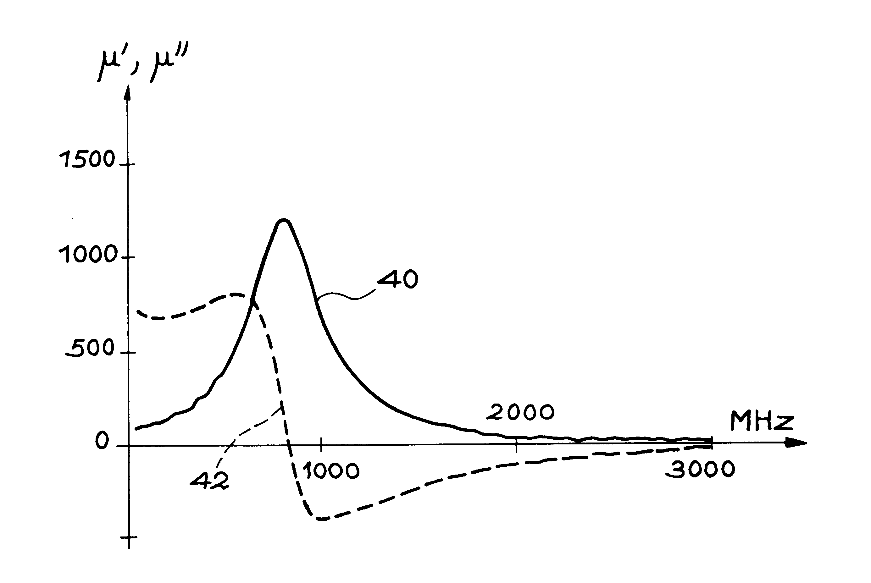
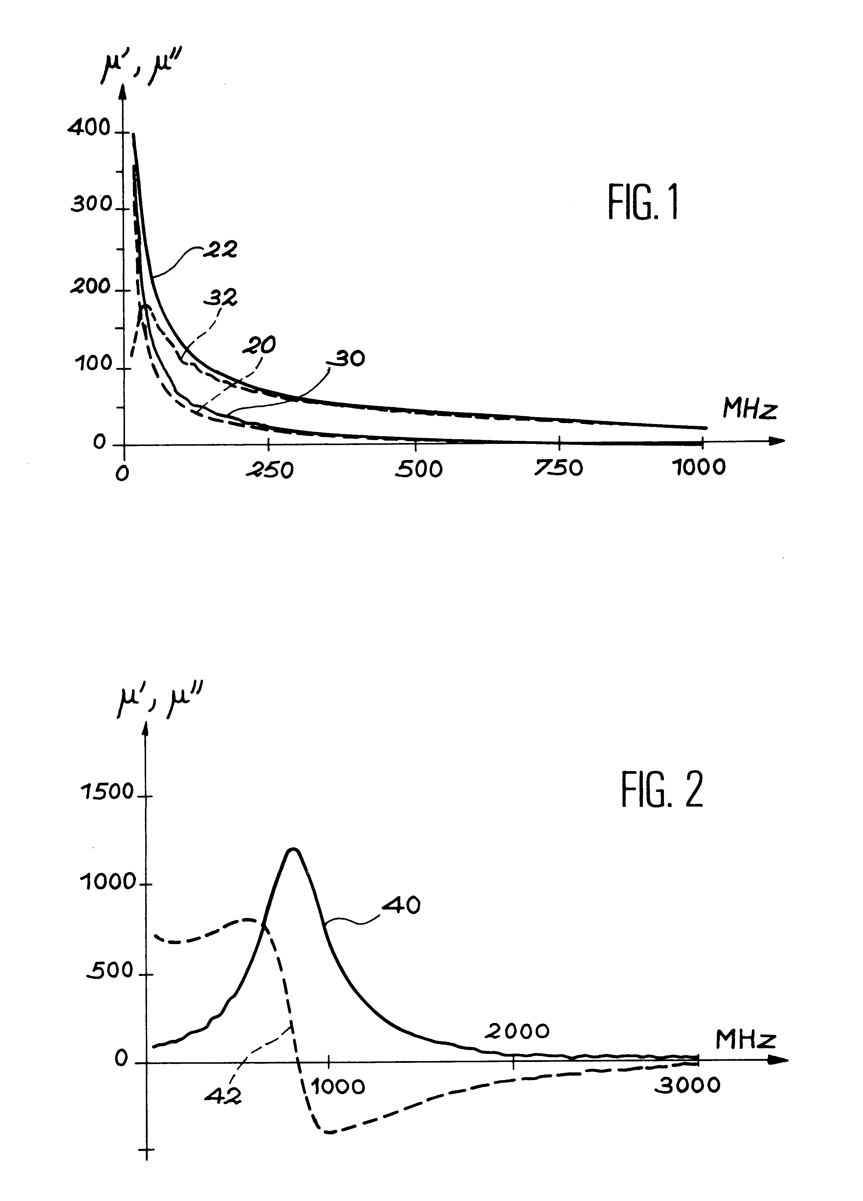
In a first embodiment, the coaxial line used is according to the APC7 standard. The insulating toric support has an inside diameter equal to the inside diameter of the central conductor of the line, which is A=2.94 mm; the outside diameter is 5.94 mm, and is therefore less than the outside diameter of the outside conductor (B=7.1 mm). The height H of the torus is 3 mm. The example magnetic material chosen is a composite glass / ferromagnetic wire (ferromagnetic composition=CoMnSiB) with diameter 2R.sub.wire =150 .mu.m. A length L=5.9 cm of wire is wound around the outside diameter P of the torus, namely 3 turns. The toric support is made of plexiglas. The fractional volume of material is then 0.8%.

The permeability .mu..sub.m of a uniform sample in a line length d is calculated either by a measurement in reflection transmission using Nicholson and Weir equations, or in front of a short circuit. It may be sufficient to measure the reflection of the wave on the sample in front of a short...

second embodiment

In a second embodiment, the coaxial line used is according to the APC7 standard. The inside diameter A of the Plexiglas toric support is the same as the inside diameter of the inner conductor =2.94 mm; the outside diameter 2P is 5.94 mm, and is therefore less than B, the outside conductor diameter (7.1 mm). The height H of the torus is 3 mm. The magnetic material is a thin ferromagnetic layer with composition CoFeMoSiB and thickness e.sub.ferro 0.227 .mu.m on a 12.7 .mu.m thick flexible substrate (kapton). A 3 mm ribbon is measured over 90 mm, namely n.sub.turns =4.75 turns. The fractional volume of the sample is 0.06%.

For thin layers sensitive to magnetostrictive effects, the direction of the winding on the ferromagnetic face on the inside or the outside creates opposite stresses that will vary the resonant frequency of the sample symmetrically about its value at the mechanical equilibrium of the film.

To compare the measurement methods, a wound torus with a load factor of 13% was b...


PUM


Abstract

The process determines the permeability of the magnetic material by disturbance of a hyper frequency coaxial line. In the process, a sample of the material is formed and placed in a hyper frequency coaxial line. The reflection and / or transmission of a hyper frequency electromagnetic wave on and / or through this coaxial line is measured and the result of this measurement is used to deduce the magnetic permeability of the material. The fractional volume of magnetic material in the sample compared with the volume of the disturbed coaxial line is less than 1%.

Description

"This application is a national phase of PCT / FR00 / 00918 which was filed on Apr. 11, 2000, and International Application No. 99 / 04726, which was filed on Apr. 15, 1999, and was not published in English."TECHNICAL DOMAINThe purpose of this invention is a process for the determination of the permeability of a magnetic material by disturbance of a coaxial line. Its applications include characterization of materials, and particularly ferromagnetic materials.STATE OF PRIOR ARTA network analyzer can be used to measure the reflection and transmission of a hyper frequency electromagnetic wave on and through a sample placed in a wave-guide. If this wave guide is a coaxial line, for example according to the APC7 standard that can carry a frequency band of up to 18 GHz, the permittivity .epsilon. and the permeability .mu. of the sample can be deduced from this measurement using the Nicholson and Weir equations [1, 2]. These equations are only applicable to a solid homogenous isotropic sample, a...

Claims


Application Information

Patent Timeline
IPC IPC(8): G01R27/26G01R33/12
CPCG01R27/2647G01R33/1223
Inventor ADENOT, ANNE LISEACHER, OLIVIER
Owner COMMISSARIAT A LENERGIE ATOMIQUE ET AUX ENERGIES ALTERNATIVES
Learn More