
Scale member, method of producing the same and displacement measuring apparatus therewith

a technology of displacement measuring apparatus and scale member, which is applied in the direction of mechanical measuring arrangement, instruments, and mechanical means, etc., can solve the problems of not measuring the periphery, complicated alignment, and non-contact measurement methods

Inactive Publication Date: 2003-12-30
MITUTOYO CORP
View PDF15 Cites 8 Cited by
  • Summary
  • Abstract
  • Description
  • Claims
  • Application Information

AI Technical Summary

Problems solved by technology

In the conventional displacement measuring apparatus of contact type, however, a probe has an order-of-magnitude smaller size compared to a work to be measured and can not contact the work directly.
The non-contact measuring methods, however, have the following problems:
(2) As a light propagates in free space, they can not measure peripheries of a complicated structure that has an obstacle to shut a light path.
The use of optical fibers can correspond to this problem but still remains the following problems:
(3) They require a complicated alignment among optical devices, have a low allowance over disturbance such as vibrations and temperature and moisture variations, and have a difficulty in high reliable and precise measurement; and
(4) They depend greatly on optical characteristics of the work (reflection coefficients, for example) and are of inferior general versatility.

Method used


Image

  • Scale member, method of producing the same and displacement measuring apparatus therewith
  • Scale member, method of producing the same and displacement measuring apparatus therewith
  • Scale member, method of producing the same and displacement measuring apparatus therewith

Examples


first embodiment

A preferred first embodiment of the present invention will be described below with reference to the accompanying drawings.

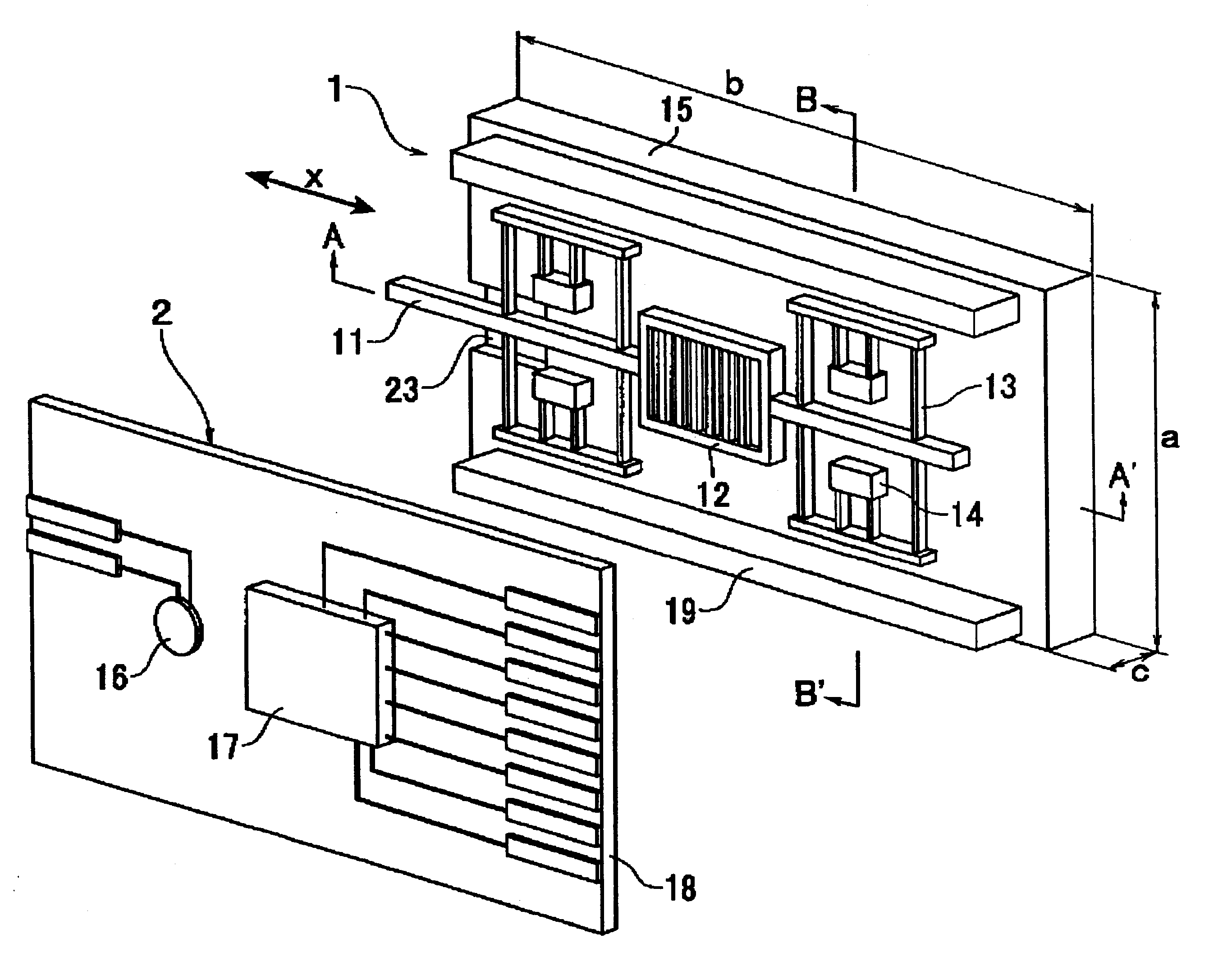
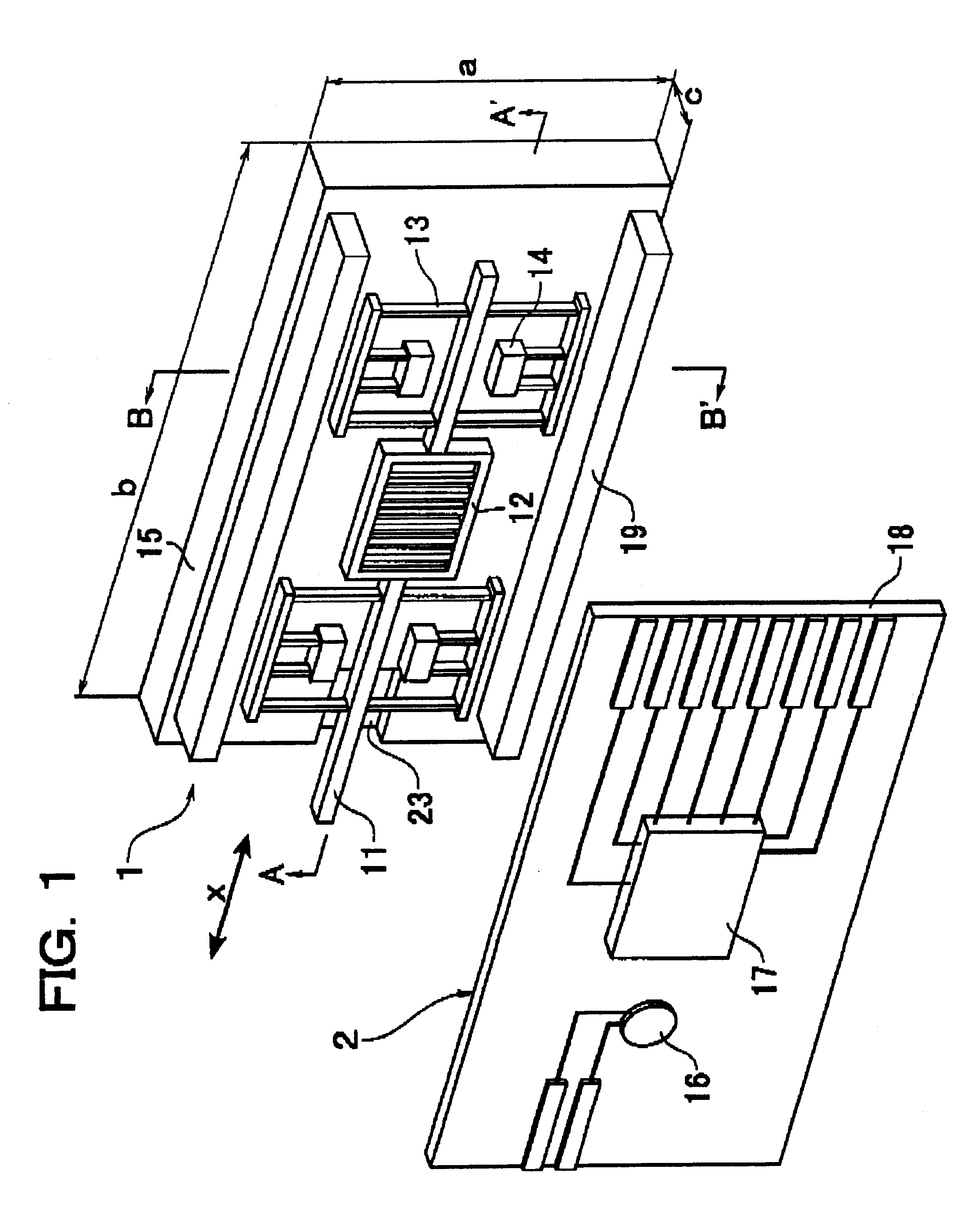
FIG. 1 is an exploded perspective view showing an arrangement of a displacement measuring apparatus according to the first embodiment of the present invention,

FIG. 2A is a cross-sectional view taken along A-A' in FIG. 1 and FIG. 2B is a cross-sectional view taken along B-B' in FIG. 1.

This displacement measuring apparatus comprises a scale member 1 and a displacement sensor 2. The scale member 1 includes a spindle 11 and a scale 12, which are movably supported by resilient supports or parallel leaf springs 13 on a scale substrate 15. In the scale member 1 the spindle 11 is arranged in coaxial with a measurement axis x. The scale 12 is integrated with the spindle 11 and supported by the parallel leaf springs 13 so as to move together with the spindle 11 along the measurement axis x. The scale 12 has an L & S slit-processed surface. These spindle 11, scale 12 and pa...


PUM

PropertyMeasurementUnit
displacementaaaaaaaaaa
displacement measuring apparatusaaaaaaaaaa
resilientaaaaaaaaaa

Abstract

There is provided a displacement measuring apparatus efficiently productive and easily applicable to high precise measurement of displacement with contact probe detection for hardly-measurable works in the art such as micro-works and deep parts in complicated structures. A scale member includes a spindle and a scale both supported by a parallel leaf spring movable on a scale substrate. The spindle is arranged in coaxial with a measurement axis in the scale member. The L & S slit-processed scale is integrated with the spindle and supported by the parallel leaf spring to move together with the spindle along the measurement axis. The spindle, scale and parallel leaf spring are coupled to the scale substrate interposing an anchor of the parallel leaf spring therebetween. The spindle, scale and parallel leaf spring are formed in an integral structure and only the anchor contacts the scale substrate while the spindle, scale and parallel leaf spring slightly float from the scale substrate. A displacement sensor comprises a sensor substrate arranged opposite to the scale substrate. A light source and a photosensitive device are located on the sensor substrate.

Description

1. Field of the InventionThe present invention relates to a contact micro-displacement measuring apparatus applicable to high precise measurement of micro-works and hardly-measurable deep parts and productive with a low cost and high precision.2. Description of the Related ArtRecent developments in micro-processing technologies such as micro-machining permit production of microstructures that have been impossible to produce by the conventional machining in the art and accordingly increase requirements for high precise measurement of micro-works.In the conventional displacement measuring apparatus of contact type, however, a probe has an order-of-magnitude smaller size compared to a work to be measured and can not contact the work directly.In addition, non-contact measuring methods such as a method using laser light are generally applied to works to which the contact measuring methods are hardly applied. The non-contact measuring methods, however, have the following problems:(1) A sp...

Claims


Application Information

Patent Timeline
Patent Type & Authority Patents(United States)
IPC IPC(8): G01D5/26G01D5/347G01B7/00G01B21/00G01D5/36G01B5/00
CPCG01D5/347G01D5/34715Y10T29/49002Y10T29/49007
Inventor SHIMOMURA, TOSHITAKATOMINAGA, ATSUSHI
Owner MITUTOYO CORP
Learn More