
Device for the separation of solid objects from a flowing fluid

Inactive Publication Date: 2003-12-23
VATTENFALL
View PDF5 Cites 43 Cited by
  • Summary
  • Abstract
  • Description
  • Claims
  • Application Information

AI Technical Summary

Benefits of technology

The present invention aims at removing the above-mentioned inconveniences of the previously known separator device and creating an improved separator device. A primary object of the invention is to create a separator device that may not only trap the solid objects that are brought by the main flow in an effective way, but also to guarantee that the trapped objects reliably remain in the collecting space during a long time, preferably during the time that goes by between two consecutive reactor revisions. Another object is to create a separator device which, when it is passed by the main fluid flow, does not give rise to flow disturbances, such as vortex formations, turbulence and similar, which in turn may cause detrimental vibrations in the conduit system downstream of the device. A further object of the invention is to create a separator device of a mechanical construction that is as simple as possible, it being possible to mount the device into existing conduit tubes. Yet another object is to create a separator device that does not cause a considerable pressure drop in the main fluid flow when it passes through the device.

Problems solved by technology

For this reason, the previously known devices are not suited for the separation of scrap from the feed water to nuclear reactors.

Method used


Image

  • Device for the separation of solid objects from a flowing fluid
  • Device for the separation of solid objects from a flowing fluid
  • Device for the separation of solid objects from a flowing fluid

Examples


Embodiment Construction

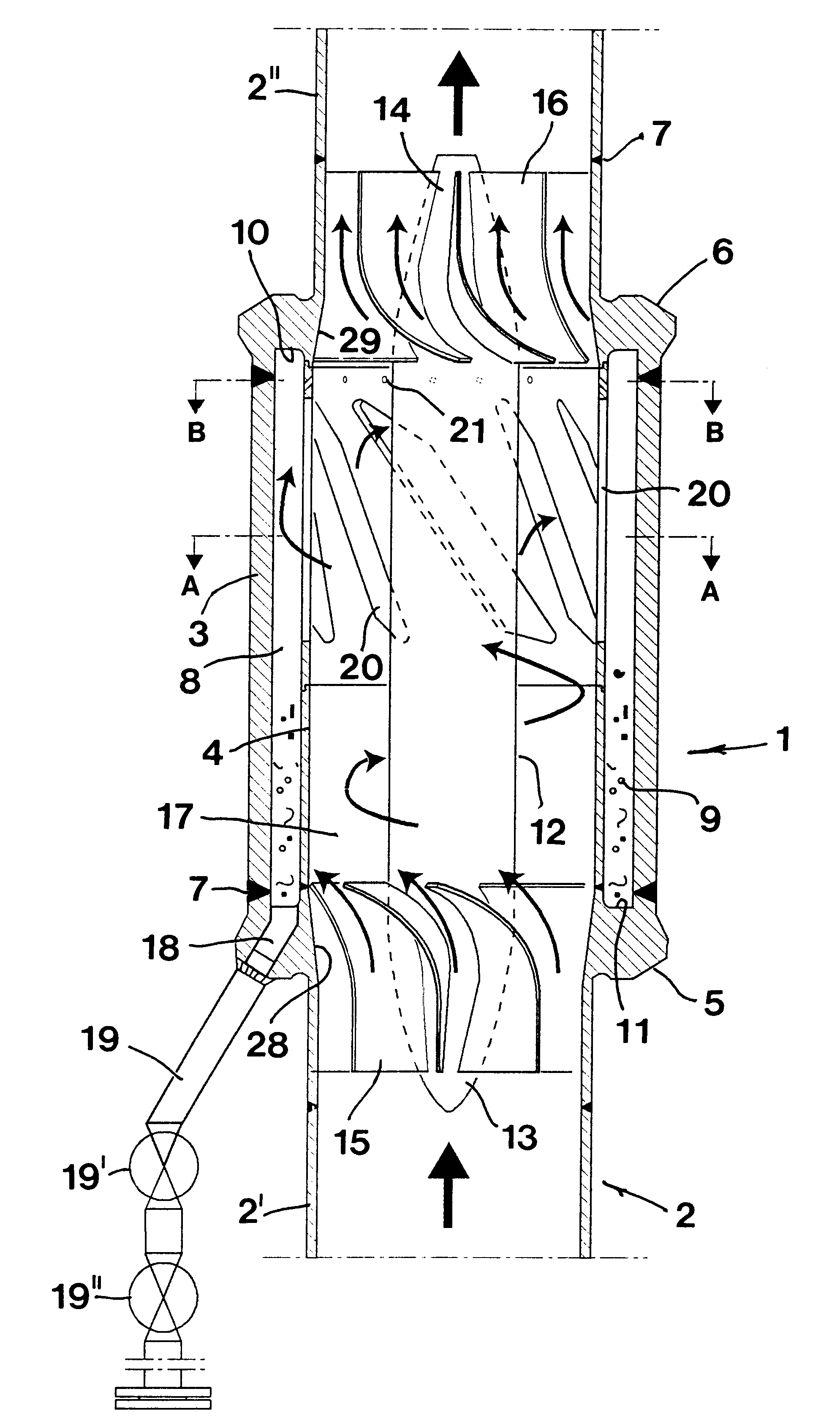
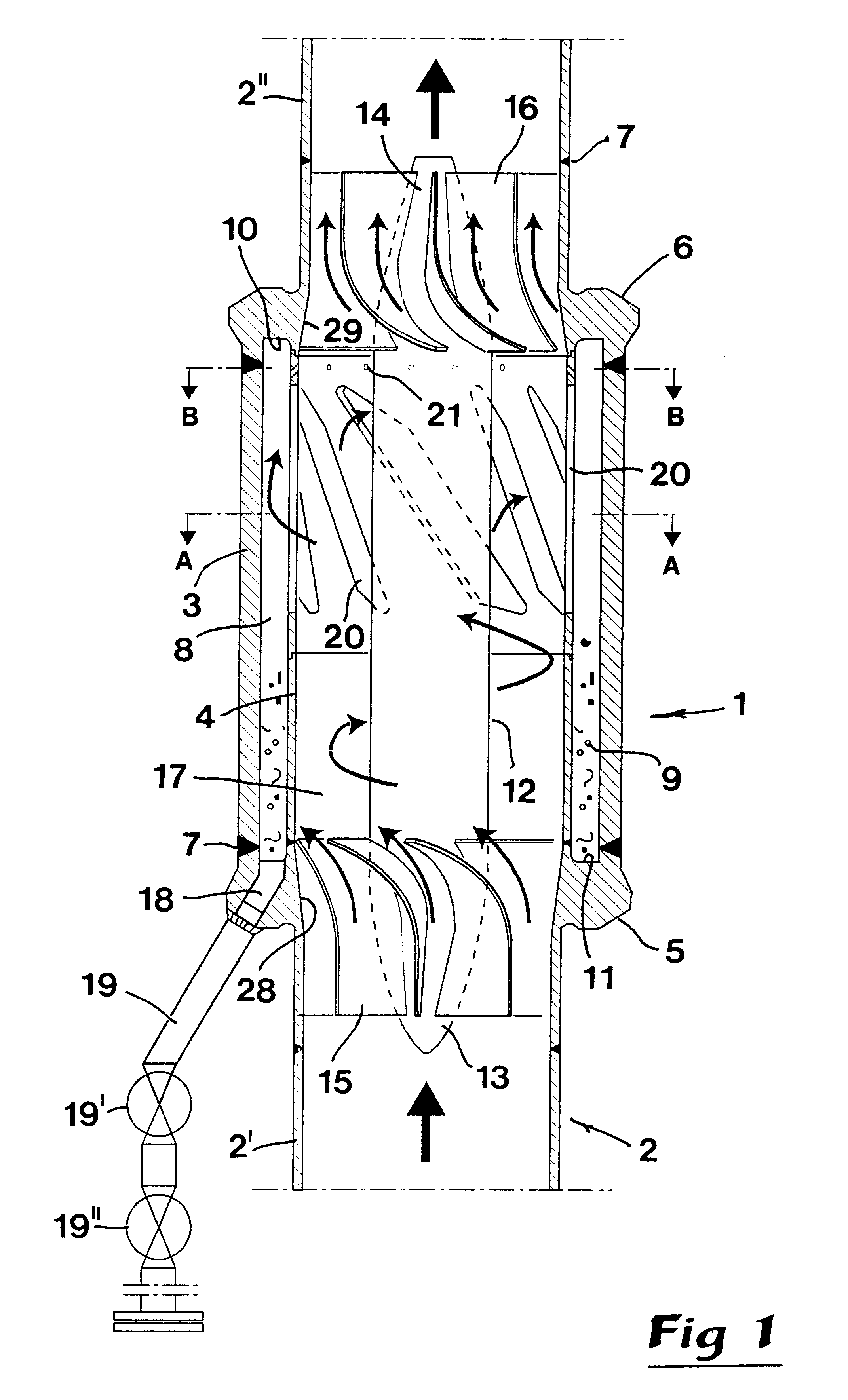
In FIG. 1, reference numeral 1 designates generally a separation device according to the invention, which is mounted in a water conduit tube 2, more specifically between a first tube part 2' at the upstream side of the device, and a second tube part 2" at the downstream side of the device. As illustrated by the two stout axial arrows, the water flow passes through the conduit tube in a direction from below and upwards, the tube being most advantageously vertically oriented, although an oblique mounting also is feasible.

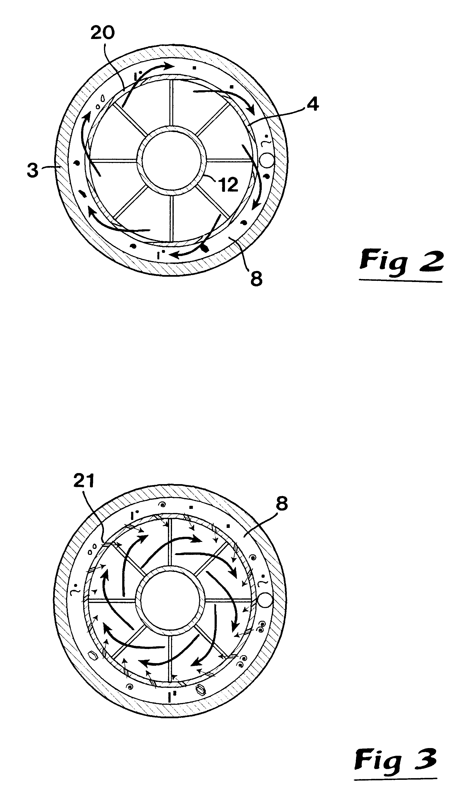
The separation device 1 includes a housing that comprises a tubular outer wall 3 and an equally tubular inner wall 4. At least the inner wall 4--but advantageously also the outer wall 3--has a rotation-symmetrical basic shape. More specifically, according to the example in FIG. 1, the two walls are cylindrical. Each one of the walls is connected to specific end pieces 5, 6, which in turn are connected to the two tube parts 2' and 2". As indicated in the drawings, said...


PUM

PropertyMeasurementUnit
Shapeaaaaaaaaaa

Abstract

A device for the separation of solid objects (9) from fluid flowing in a conduit tube (2) includes a housing that includes a tubular outer wall (3) and a tubular inner wall (4). Between these is delimited a collecting space (8). Concentrically relative to the inner wall (4) is provided a rotation-symmetrical central body (12) which at opposing ends cooperates with flow converting devices (15, 16), which transform incoming flow to a rotative motion and outgoing flow to an axial motion. In the inner wall (4) are recessed tangentially separated holes (20) of elongated shape, through which the scrap objects may pass and be collected in a collecting space (8). In the collecting space (8) a calm flow operation is obtained which guarantees that collected scrap objects are not carried away and returned to the main fluid flow through the separation device.

Description

This invention relates to a device for the separation of solid objects from a fluid flowing in a conduit tube, comprising a housing mounted between separate parts of the tube, which housing comprises a tubular outer wall and a tubular inner wall of a rotation-symmetrical basic shape, a ring-shaped collecting space being delimited between said walls, and a central body of a rotation-symmetrical basic shape placed concentrically relative to the inner wall, which central body at an inlet end cooperates with a first fluid converting device having the purpose of transforming an arriving axial fluid flow into a substantially rotating flow in a ring-shaped space between the central body and the inner wall, and at an outlet end cooperates with a second flow converting device with the purpose of transforming the rotating fluid flow in the latter ring space into an outgoing axial flow in the tube part that is located downstream of the housing, the inner wall having passages through which obje...

Claims


Application Information

Patent Timeline
IPC IPC(8): B04C3/00B04C3/06
CPCB04C3/00B04C3/06B04C2003/006
Inventor HENRIKSSON, MATSLUNDSTROM, ANDERSKARLSSON, ROLFKAIPANEN, TAPIOWESTIN, JOHAN
Owner VATTENFALL
Learn More