Telescoping filling head

Inactive Publication Date: 2003-12-16
STOVER CLIFFORD W +2
View PDF15 Cites 7 Cited by
  • Summary
  • Abstract
  • Description
  • Claims
  • Application Information

AI Technical Summary

Benefits of technology

It is a further object of an exemplary form of the present invention to provide a filling head for a rotary filling device that permits the introduction of foaming liquids into a bottle more quickly than the currently available filling heads.
It is a further object of an exemplary form of the present invention to provide a filling head for a filling device which can precisely direct the product flow toward the shoulders of the bottle being filled.
It is a further object of an exemplary form of the present invention to provide a filling head for a rotary filling device in which the nozzle depth can be precisely adjusted for use with bottles which have different neck and shoulder configurations.

Problems solved by technology

This traditional setup is difficult to use to fill tall bottles with liquids, as the liquids tend to foam.
In an existing filling device the amount a bottle can be elevated is limited by the structure of the machine.
Thus it may be impossible, particularly when filling tall bottles, to use any currently available longer nozzle to avoid the problem of foaming during filling.
This is because there is often insufficient room to lift the bottle enough to accommodate a nozzle that is long enough to dispense the liquid at an appropriate depth.
Therefore manufacturers have been forced to use shorter nozzles, which require elevating the bottle less.
In addition, when a shorter nozzle must be used with a bottle with a long neck, the longest nozzle that may be accommodated in the existing structure of the filling device may not reach below the neck of the bottle.
These practices increase production costs for the product.
In addition, even where the existing structure of the rotary filling device does not limit the amount the bottle can be elevated, the process of elevating the bottle, and precisely guiding a protruding nozzle into the bottle, slows the filling process.

Method used


Image

  • Telescoping filling head
  • Telescoping filling head
  • Telescoping filling head

Examples


Embodiment Construction

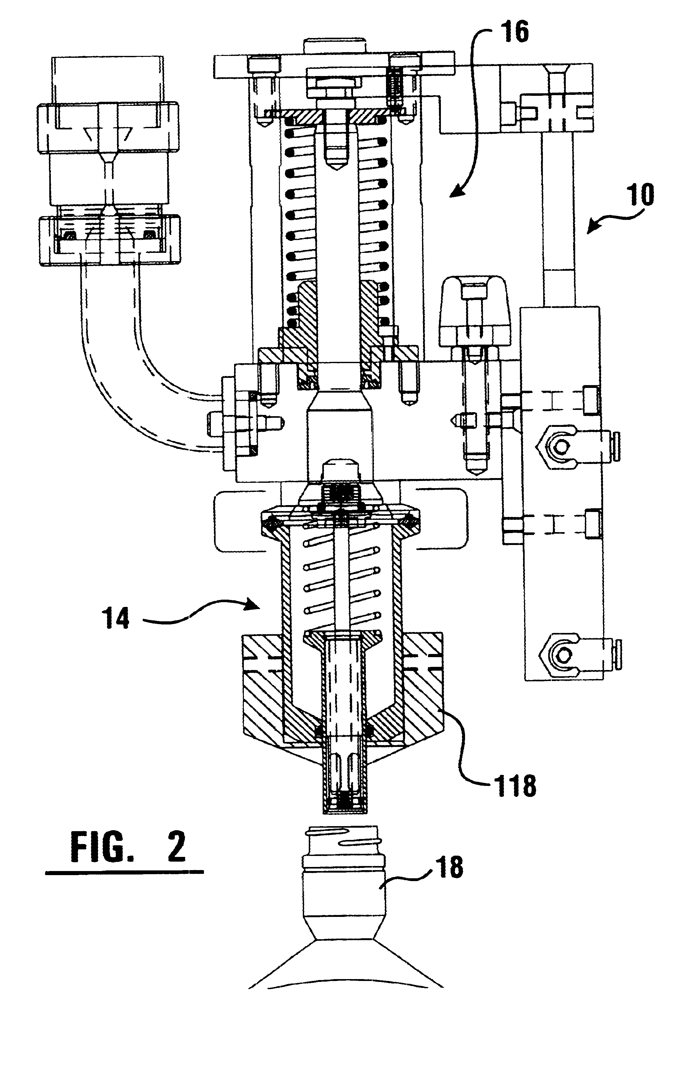
Referring now to the drawings, and particularly to FIGS. 1 and 2, there is shown therein an exemplary embodiment of a telescoping filling head, generally indicated 10. The telescoping filling head 10 includes a nozzle portion 14, a driving portion 16, a driving arm 28, and an air cylinder 20. The air cylinder 20, driving arm 28, and driving portion 16 are adapted to extend and retract the nozzle portion 14.

In an exemplary embodiment, the nozzle portion 14 may be driven by an air cylinder 20. It should be understood that in other embodiments it may be driven by other devices adapted to telescope and retract the nozzle portion 14 of the telescoping filling head 10, including hydraulic devices, motors, or other fluid, mechanical, or electrical driving devices. In addition, although in this exemplary embodiment the air cylinder 20 is shown in parallel with the nozzle and driving portions 14, 16 of telescoping filling head 10, in other embodiments it may be placed in series with the nozz...


PUM

PropertyMeasurementUnit
Timeaaaaaaaaaa
Timeaaaaaaaaaa
Forceaaaaaaaaaa

Abstract

A telescoping filling head comprising a driving portion, a nozzle block portion and a two-stage telescoping nozzle, the innermost portion of the nozzle having positionable apertures. A telescoping filling head can be retrofitted on an existing filling device, or can be incorporated in a newly manufactured filling device. The telescoping action permits a longer nozzle to be used in any given space, because the two portions which extend to create a relatively long filling nozzle retract within a relatively short outer nozzle. The longer nozzle increases the rate at which foaming liquids can be introduced into a container. The positionable apertures can also direct the flow of the liquid at the shoulders of the bottle, further increasing the rate at which foaming liquids can be introduced into a container.

Description

This invention relates to filling heads for bottling machines. Specifically, this invention relates to a telescoping filling head which extends from its rest position in two stages, diminishing the need to elevate the bottle onto the nozzle. This filling head may be used to retrofit an existing machine to improve performance when adequate elevation of the existing filling head cannot be obtained. In addition this filling head may be incorporated into new machines to speed up the rate at which liquid can be dispensed into the bottles.Liquid filling heads for rotary filling devices are known in the prior art. When a rotary filling device is used in a traditional manufacturing environment, each bottle is elevated to a bottle guide on the filling head. The bottle is held between a bottle guide and a support plate while the bottle is filled using a nozzle which extends through, or is flush with, the bottle guide. This traditional setup is difficult to use to fill tall bottles with liquid...

Claims


Application Information

Patent Timeline
IPC IPC(8): B67C3/26B67C3/02
CPCB67C3/26
Inventor STOVER, CLIFFORD W.RYBERG, ERIK R.BIGGINS, JR., HOWARD J.
Owner STOVER CLIFFORD W
Why Eureka
Try Eureka