
Spacer microparticle spraying apparatus and method for fabricating a liquid crystal display

a technology of liquid crystal display and spraying apparatus, which is applied in the direction of electrostatic spraying apparatus, coatings, instruments, etc., can solve the problems of aggravated display quality, inability to utilize above technologies, and decreases in contrast and tone, so as to prevent short-circuiting of surface electrodes, accurate dumping, and improved selectivity of disposing microparticles

Inactive Publication Date: 2003-11-18
SHARP KK
View PDF4 Cites 24 Cited by
  • Summary
  • Abstract
  • Description
  • Claims
  • Application Information

AI Technical Summary

Benefits of technology

The microparticles which can be disposed by means of the spraying apparatus according to the first aspect of the present invention is not particularly restricted but may be metallic microparticles, synthetic resin microparticles, inorganic microparticles, and light-opaque microparticles comprising a dispersion of pigment particles in a synthetic resin matrix, colored microparticles, microparticles responsive to heat or light to develop adhesion, and metal, synthetic resin or inorganic microparticles whose surfaces have been plated with a metal, among others. The method of spraying said microparticles may be whichever of dry and wet spraying methods. In the wet spraying system, the spacer is dispersed in a mixed solvent such as water-alcohol but since the spacer can be charged even under such conditions, the effects of the invention are not comprised. However, since microparticles with a larger charging amount can be more accurately disposed, the dry spraying system is preferred.

Problems solved by technology

In addition, the orientation of liquid crystals on the spacer surface is disturbed to cause escape of light, resulting in decreases in contrast and tone to aggravate the display quality.
However, any method as mentioned above invariably depends on the use of wiring electrodes and, therefore, are only applicable to TFT liquid crystal display devices.
In STN liquid crystal display devices, there are no electrodes corresponding to said wiring electrodes but stripe electrodes are disposed in orthogonal relation between the two substrates to form pixel electrodes, with the areas corresponding to the black matrix forming the electrode gaps (spaces), with the result that the above technologies cannot be utilized.
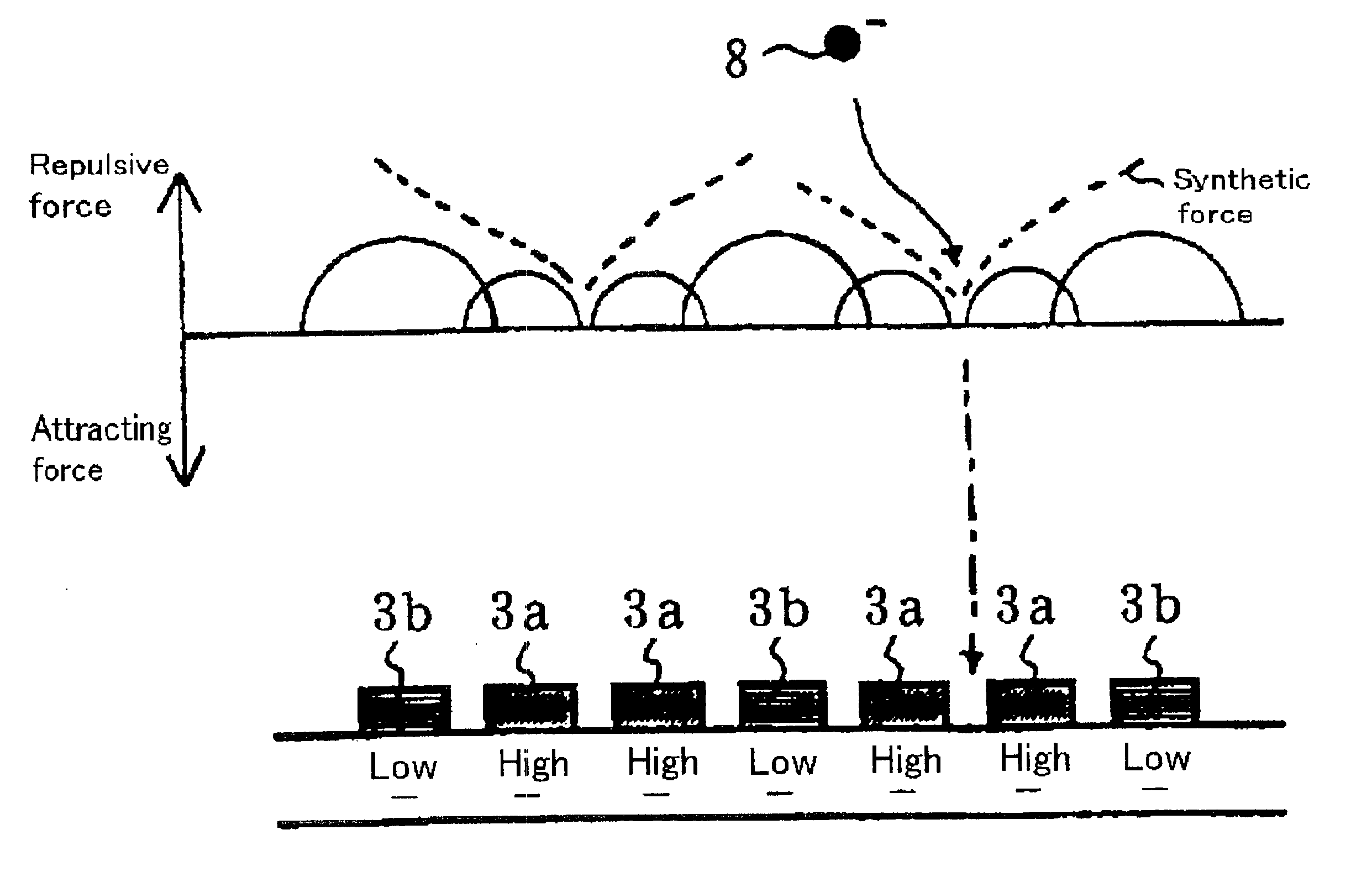
However, with this spacer spraying apparatus, the falling speed of spacer microparticles can be controlled in some measure by exploiting the influence of an electric field but since lines of electric force are formed between the top and bottom electrodes, selective control of spacer falling position is difficult.
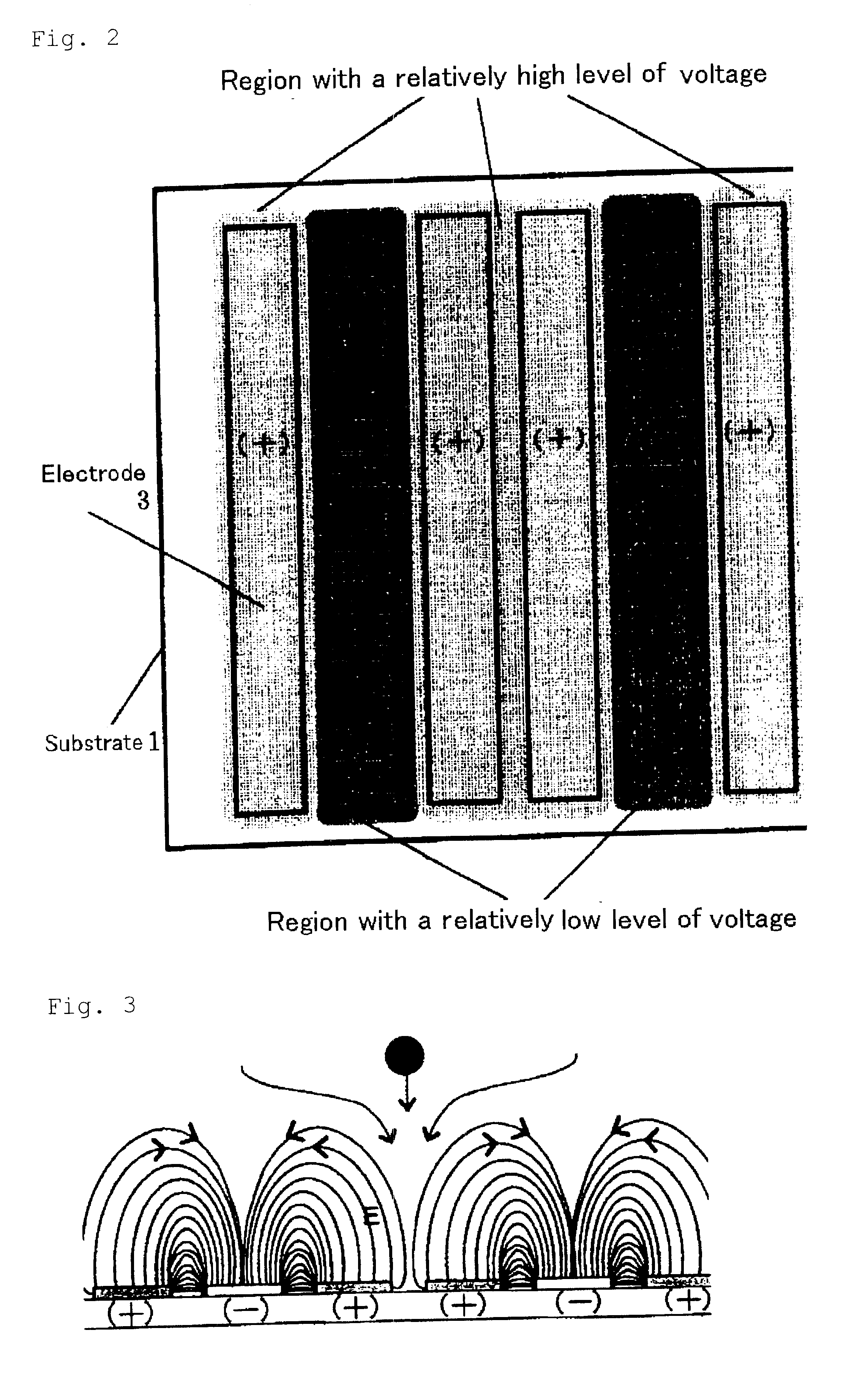
Moreover, when a voltage is applied to the stripe electrode array for use as bottom electrodes, no selectivity is obtained but a uniform electric field prevails because of the narrow electrode gaps in the liquid display device.
Thus, it is even more difficult to dispose the spacer selectively in the electrode gaps where no pixels exist.
However, this spacer spraying apparatus is not designed for selective control of spacer falling position and incapable of preventing disposition of spacer microparticles on the display areas of the liquid crystal display device.

Method used


Image

  • Spacer microparticle spraying apparatus and method for fabricating a liquid crystal display
  • Spacer microparticle spraying apparatus and method for fabricating a liquid crystal display
  • Spacer microparticle spraying apparatus and method for fabricating a liquid crystal display

Examples


example 2

Except that the spraying time was set to 20 seconds and the voltage was applied under the same conditions as in Example 1 for an initial 10 seconds and thereafter in the reversed polarity for the remaining 10 seconds, the spacer was sprayed in otherwise the same manner as in Example 1.

Microscopic examination of the substrate sprayed with the spacer as above revealed that, in addition to the same disposition lines as in Example 1, the spacer had been disposed between the other comb-shaped electrodes (at intervals of every two stripe electrodes). The number of spacer microparticles on the substrate was counted and converted to the count per mm.sup.2. The result was 200 / mm.sup.2.

example 3

Except that the humidity controller was switched OFF and, instead, the spraying chamber was purged with dry nitrogen gas, the spacer was sprayed in otherwise the same manner as Example 1.

Microscopic examination of the substrate sprayed with the spacer as above showed that the spacer had been disposed in the same pattern as in Example 1.

example 4

Except that a prover-like terminal device capable of energizing every two stripe electrodes at two-electrode intervals was prepared and connected to both sides so that voltage could be applied to the individual electrodes in the stripe direction of the ordinary common substrate, the spacer was sprayed in otherwise the same manner as in Example 1.

Microscopic examination of the substrate sprayed with the spacer as above revealed that the spacer had been disposed in the same pattern as in Example 1.


PUM


Abstract

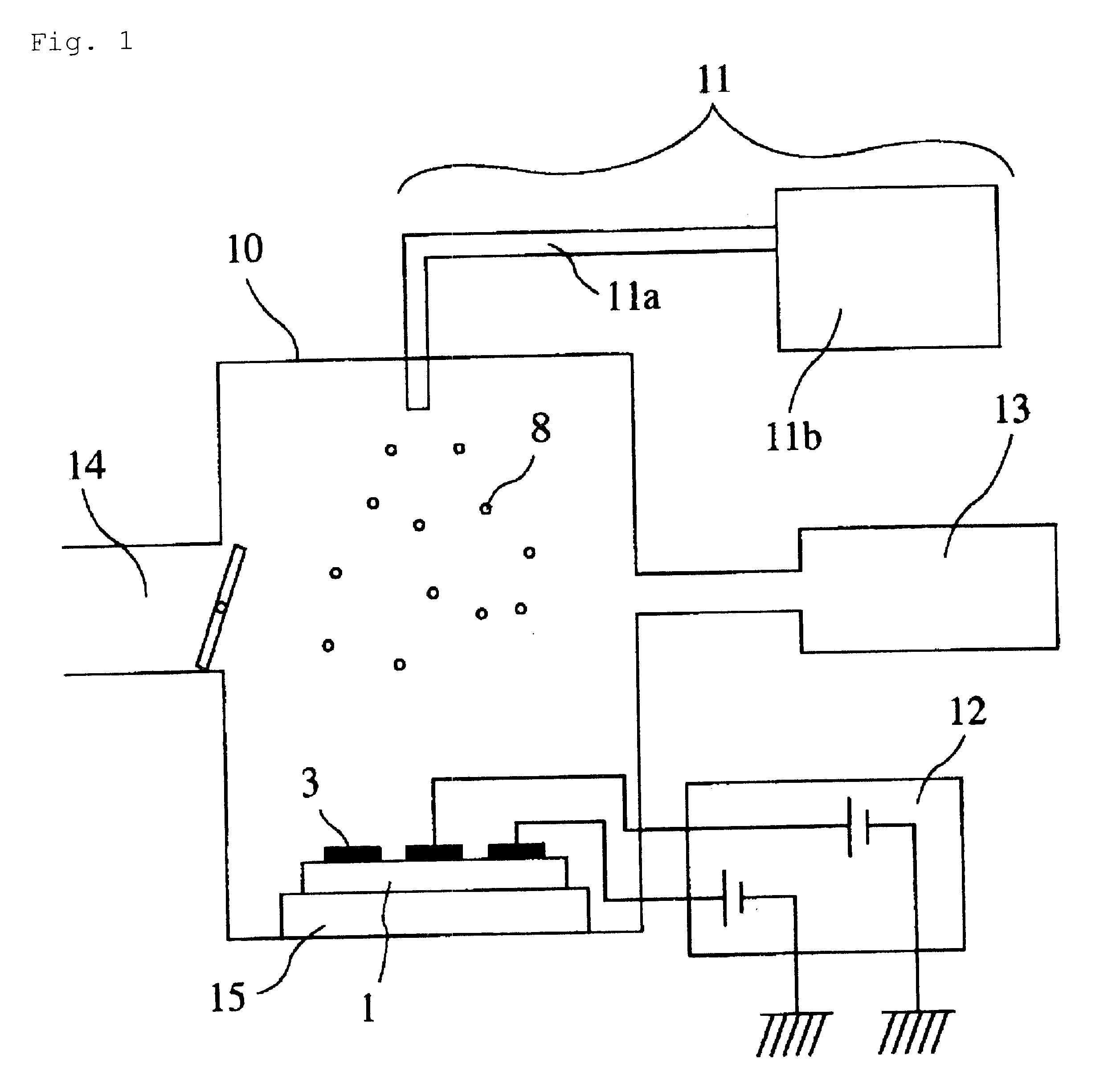
Provided is a spacer microparticle spraying apparatus capable of selectively disposing spacer microparticles in electrode gaps where no pixels are present even on a substrate carrying an array of stripe electrodes in use for the STN liquid crystal display device, to a spacer particle spraying method and a method of manufacturing a liquid crystal display device which utilize said apparatus. The spacer microparticle spraying apparatus for selective disposition of a charged spacer microparticle on a substrate carrying a plurality of electrodes includes a spraying chamber adapted to accommodate the substrate, a spacer microparticle supply means for supplying the spacer microparticle into the spraying chamber and spraying it on the substrate, and a voltage application means for applying voltages to the electrodes disposed on the substrate, wherein the voltage application means is capable of applying different levels of voltages to the electrodes respectively.

Description

The present invention relates to a microparticle spraying apparatus and to a microparticle spraying method and a method of manufacturing a liquid crystal display device, which utilize said apparatus.With advances in electronics, microfine microparticles are used in a variety of applications. Among such microparticles are electrically conductive microparticles in use in anisotropic films, conductive microparticles in use in the field of bonding technology, and microparticles applied as spacers in liquid crystal display devices.As one of the applications of such microparticles, the liquid crystal display devices have been broadly used in personal computers and portable electronic appliances. The liquid crystal display device generally comprises a pair of substrates 1, a liquid crystal layer 7 sandwiched therebetween, a color filter layer 4, a black matrix layer 5, a transparent electrode layer 3, alignment layers 9, etc. as illustrated in FIG. 12. Here, it is a spacer layer 8 that def...

Claims


Application Information

Patent Timeline
IPC IPC(8): G02F1/13G02F1/1339
CPCG02F1/13394B05B5/053
Inventor TATENO, AKIHIKONAKATANI, HIROYUKIYOSHIMURA, KAZUYANAKAHARA, MAKOTOKIRA, TAKATOSHIIKESUGI, DAISUKEBAN, MASAKIMURATA, HIROSHIKUBO, MASAAKI
Owner SHARP KK
Learn More