
Transmission system for vehicle

a transmission system and vehicle technology, applied in the direction of fluid gearings, transportation and packaging, gearing, etc., can solve the problems of affecting the driving experience of the driver,

Inactive Publication Date: 2003-11-18
SUBARU CORP
View PDF9 Cites 20 Cited by
  • Summary
  • Abstract
  • Description
  • Claims
  • Application Information

AI Technical Summary

Problems solved by technology

However, a prior art dry clutch type AMT has difficulty generating such a positive and continuous creep for a long time as obtainable in a conventional torque converter type automatic transmission.
As a result, this type transmission provides a driver with an awkward drive feeling different from that experienced with a conventional automatic transmission vehicle when a vehicle travels at very low speeds, such as when parking, starting on grades and the like.
However, in designing the main clutch, it is very difficult to satisfy both characteristics, a characteristic for smoothly transmitting power of an engine to the input shaft and a characteristic for enduring continuous slippage.
Further, a complicated slip control of the transmission system and some forced cooling device are required, this increasing the manufacturing cost of the transmission.
In a case where a conventional torque converter is incorporated into a clutch housing for a manual transmission vehicle, it is easy to obtain a creep effect and a torque amplitude effect but a continuous delivery of drag torque of the torque converter incurs failures such as gear clash unless the torque delivery is shut off at gearshifting.
In this case, since it is difficult to install a hydraulically controlled lock-up clutch for the structural reason, the torque converter is always in a slip condition and accordingly improved fuel economy can not be expected.
Further, this transmission has disadvantages in a shift shock which occurs when the friction clutch is reengaged and a shift time elongated by the release and reengagement actions of the friction clutch.

Method used


Image

  • Transmission system for vehicle
  • Transmission system for vehicle
  • Transmission system for vehicle

Examples


Embodiment Construction

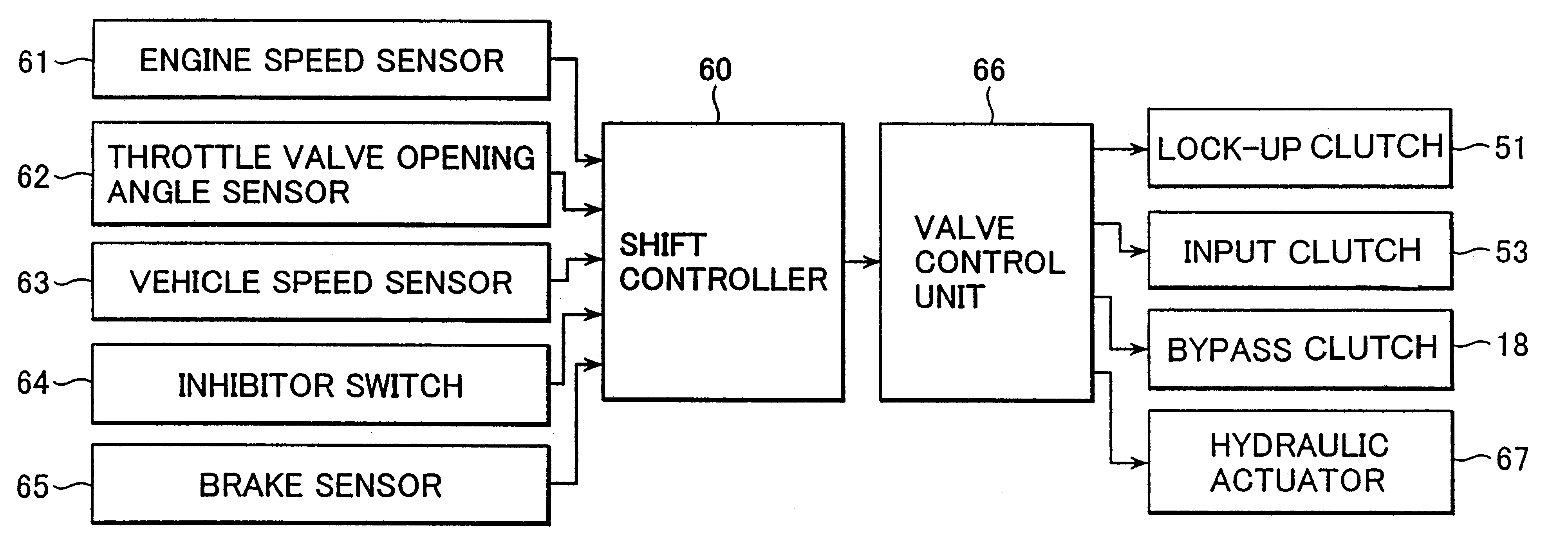
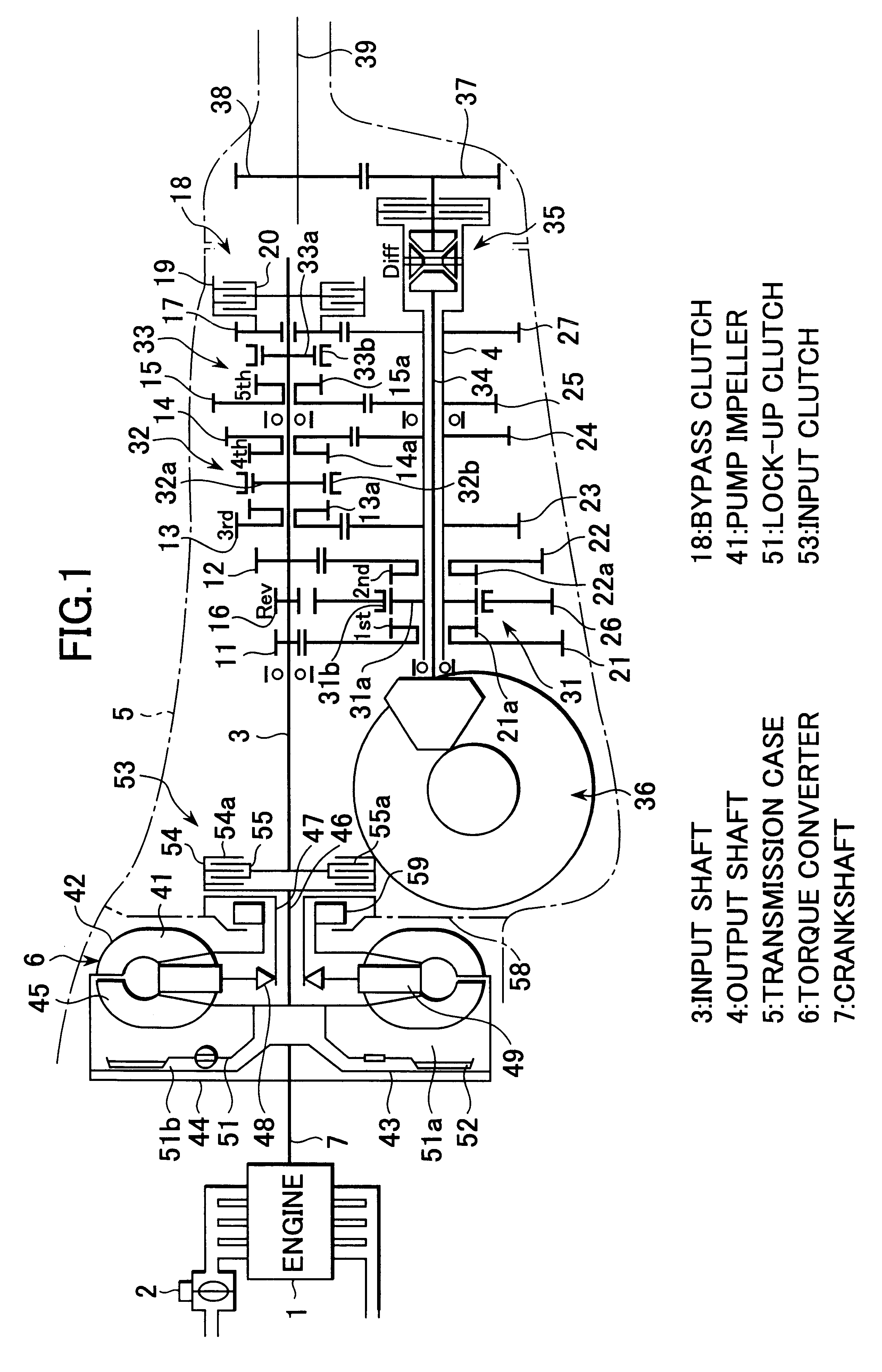
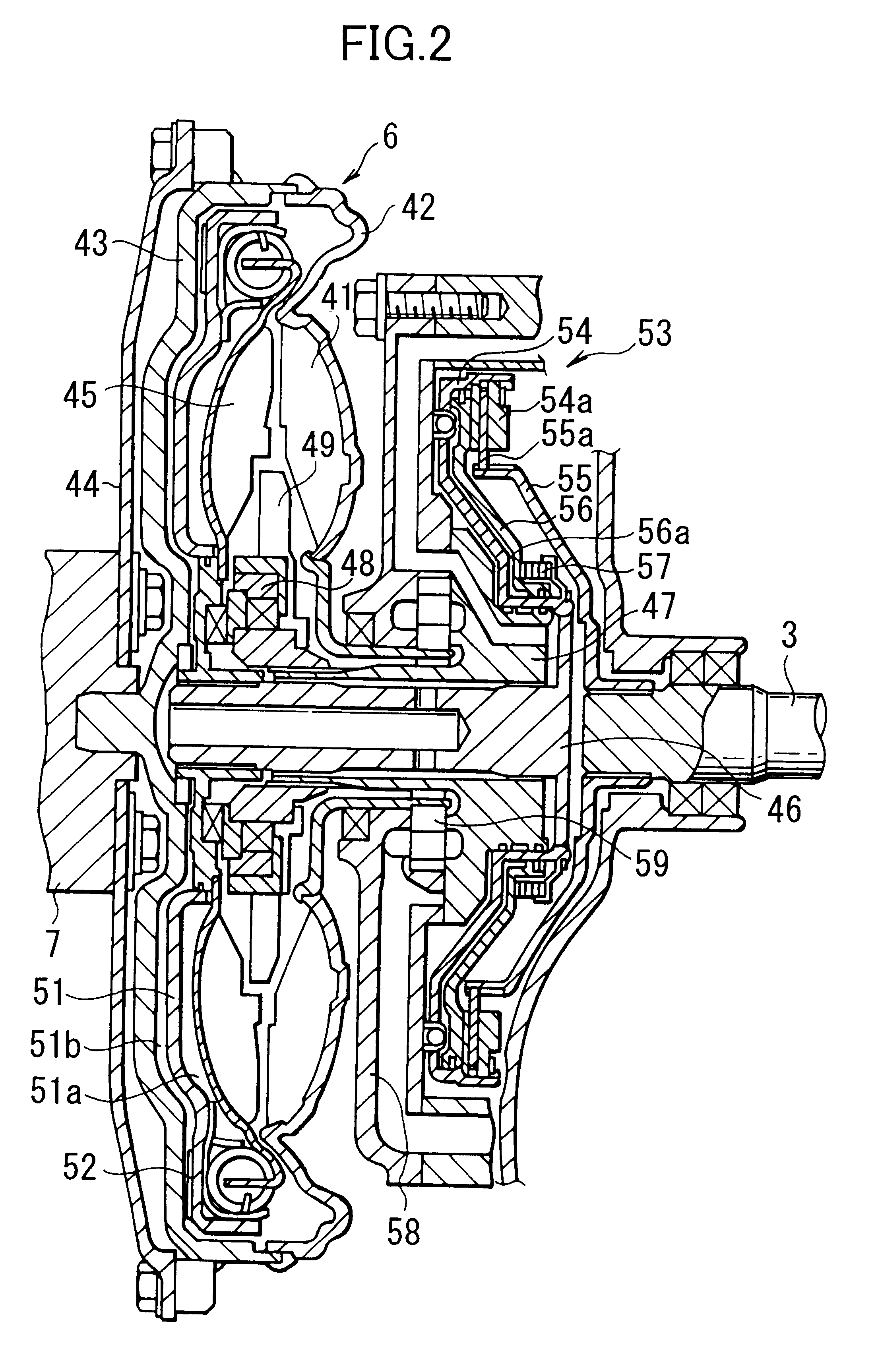
Referring to FIG. 1, an engine 1 is provided with an electronic control throttle valve 2 for controlling engine torque and engine speeds. Normally, the electronically controlled throttle valve 2 is opened and closed by output signals from an electronic control unit (not shown) according to the amount of depression of an accelerator pedal (not shown) to control the engine 1. Further, when needed, the electronically controlled throttle valve 2 is opened and closed to control the engine 1 based on a preestablished table irrespective of the amount of depression of the accelerator pedal.

Further, a transmission system for transmitting power of the engine 1 to driving wheels is exemplified as a transmission system used for a four wheel drive vehicle in this embodiment. The transmission system is mounted on a vehicle in a longitudinal direction thereof and has an input shaft 3 connected to the engine 1 and an output shaft 4 connected to driving wheels and disposed in parallel with the input...


PUM


Abstract

Vehicle automatic transmission system having input shaft drive gears, output shaft driven gears meshing with the drive gears, a torque converter disposed between an engine crankshaft and the input shaft, synchromesh mechanisms for synchronously engaging the drive gears with the driven gears and a shift controller for automatically actuating the synchromesh mechanisms to obtain a required gear ratio. A lock-up clutch is incorporated in the torque converter for connecting a turbine shaft of the torque converter with the crankshaft. An electronically controlled throttle valve automatically operates to reduce crank shaft rotation speed when the gear is shifted, a bypass clutch transmits torque from the input shaft to the output shaft when the gear is shifted while the electronically controlled throttle valve reduces rotation speed of the crankshaft, and an input clutch selectively controls torque transmission from the crankshaft to the input shaft when the gear is shifted.

Description

1. Field of the InventionThe present invention relates to a transmission system for a vehicle and more particularly to an automatic transmission whose gear trains are originated from those of a conventional manual transmission.2. Discussion of Prior ArtGenerally, a manual transmission, in which the gear is manually shifted, has an input shaft directly connected to an engine and including a plurality of drive gears and has an output shaft including a plurality of driven gears paired with the corresponding drive gears and connected to drive wheels. That is, there are provided a plurality of shift gear trains between the input shaft and the output shaft. When a gear is changed, after a clutch is disengaged, changeover mechanisms such as a synchromesh mechanism are manually operated to change over paired shift gear trains and then the clutch is engaged. This sequence of manual operations accomplishes a gear shift of a vehicle.The manual transmission can be converted into an automatic tr...

Claims


Application Information

Patent Timeline
IPC IPC(8): F16H3/08F16H3/12B60K17/346B60K17/344F16H61/04B60W10/02B60W10/06B60W10/10B60W30/18F16H3/089F16H45/00F16H45/02F16H47/00F16H63/50
CPCB60W10/02B60W10/06B60W10/11B60W30/19F16H45/02F16H61/0403B60K17/3462Y10T477/677B60K2741/286F16H3/089F16H3/12F16H45/00F16H63/502F16H2045/005F16H2061/0407F16H2061/0429Y10T74/19158Y10T477/6337Y10T477/63385Y10T477/63393Y10T477/6388Y10T477/6333Y10T74/19251B60K2741/065B60W10/04B60W10/10B60W30/1819
Inventor KOBAYASHI, TOSHIO
Owner SUBARU CORP
Learn More