
State determining apparatus for exhaust gas recirculation system

a technology of exhaust gas recirculation and state determination, which is applied in the direction of electrical control, combustible gas purification/modification, separation processes, etc., can solve the problems of failure to determine the apparatus, low responsibility, and inherently slow temperature change, and achieve efficient determination of leakage and correlation high

Inactive Publication Date: 2003-11-18
HONDA MOTOR CO LTD
View PDF6 Cites 20 Cited by
  • Summary
  • Abstract
  • Description
  • Claims
  • Application Information

AI Technical Summary

Benefits of technology

According to this state determining apparatus, the humidity of exhaust gases in the EGR passage (hereinafter called the "EGR gas") is detected by the humidity sensor arranged in the EGR passage, and the state of the exhaust gas recirculation system including the EGR passage is determined by the exhaust gas recirculation system state determining means based on the result of detection. Since the EGR gas is a portion of exhaust gases generated by combustion, it generally includes a large amount of moisture, and therefore the humidity reflects the state of the exhaust gas recirculation system including the EGR passage through which the EGR gas passes. It is therefore possible to appropriately determine the state of the exhaust gas recirculation system including the EGR passage, for example, a failure due to a leak and the like in the EGR passage based on the result of detection made by the humidity sensor. Also, since the humidity is characteristically high in responsibility and less susceptible to other factors, as compared with the temperature, a higher determination accuracy can be achieved than when the temperature is used as a parameter.
According to this preferred embodiment, the EGR passage is used as a passage for recirculating hydrocarbons desorbed from the adsorbent, on which they have once been adsorbed, to the intake system. Also, since the adsorbent is capable of adsorbing moisture as well as hydrocarbons, there is a mutually close relationship between hydrocarbons and moisture with respect to their adsorption and desorption states, and they have a high correlation. Stated another way, the humidity of the EGR gas reflects not only the state in the EGR passage but also the state of the adsorbent during desorption. It is therefore possible to appropriately determine based on the result of detection made by the humidity sensor the state of the adsorbent, for example, whether or not hydrocarbons have been completely desorbed from the adsorbent.
In a general EGR device, a majority of EGR passage is formed in a cylinder block of an engine, and the EGR passage has a relatively short length around the engine, so that a leak from the EGR passage does not cause a grave problem. On the other hand, an EGR passage containing an adsorbent as described above is often formed as a relatively long EGR pipe for connecting the downstream side of the adsorbent to an intake system, so that the EGR pipe is more susceptible to a leak due to cracking and the like possibly caused by vibrations of the engine and the difference in thermal expansion in the exhaust system. According to this preferred embodiment, it is possible to efficiently determine a leak from the EGR passage and the state of the adsorbent in such a situation based on the result of detection made by the common humidity sensor.

Problems solved by technology

However, characteristically, the "temperature" is inherently slow in change, low in responsibility, and susceptible to a variety of factors such as an external air temperature and the like.
With such characteristics of the temperature, the failure determining apparatus may fail to appropriately determine a failure of the EGR control valve, and would suffer from a lower accuracy of determination when it is applied to the determination of a leak on the EGR passage or the like, due to a large length of the EGR passage which causes the characteristics of the temperature to prominently appear.

Method used


Image

  • State determining apparatus for exhaust gas recirculation system
  • State determining apparatus for exhaust gas recirculation system
  • State determining apparatus for exhaust gas recirculation system

Examples


Embodiment Construction

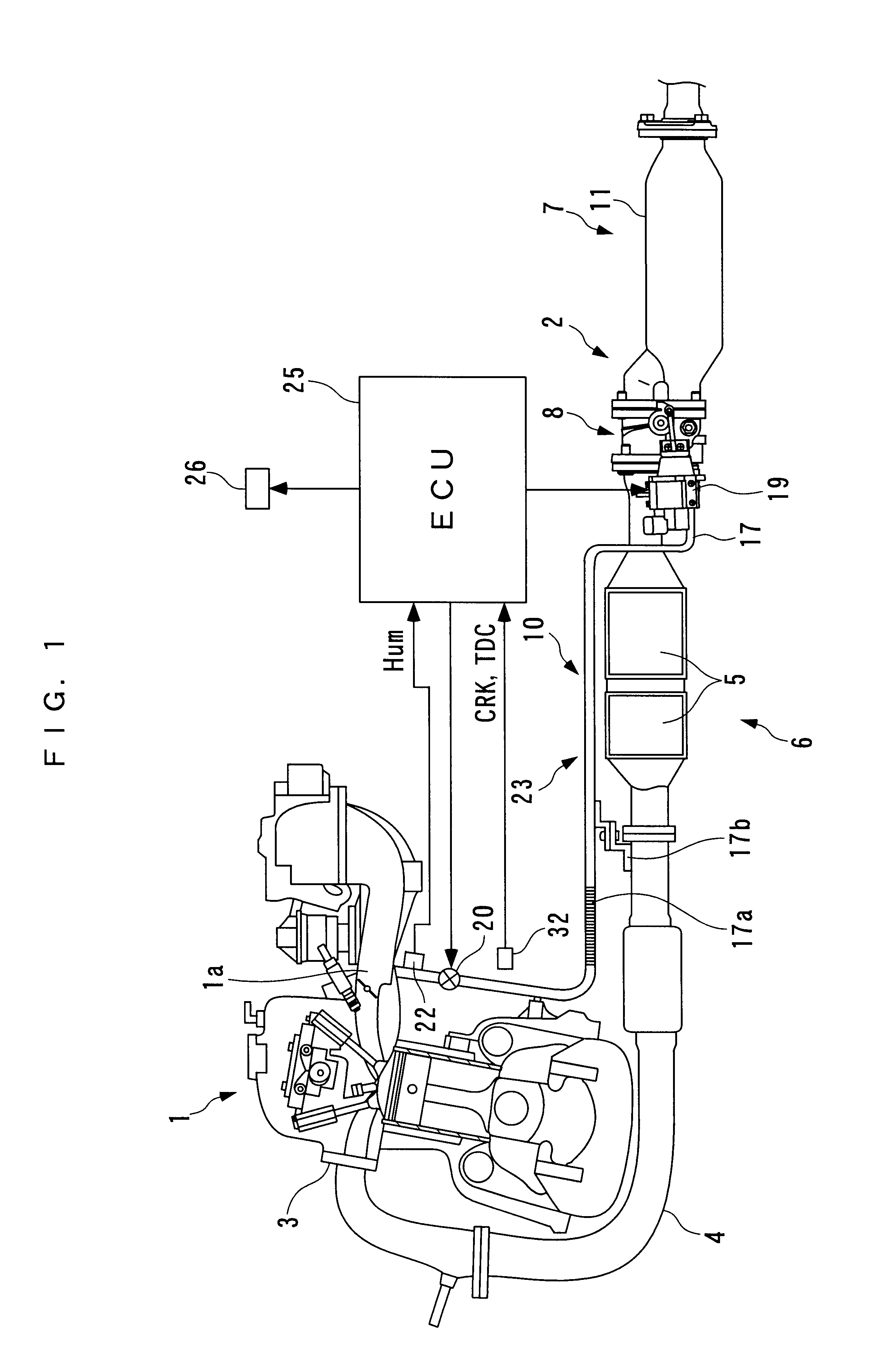
In the following, a preferred embodiment of the present invention will be described in detail with reference to the accompanying drawings. FIG. 1 illustrates an internal combustion engine in which the embodiment of the present invention is applied. In the illustrated internal combustion engine (hereinafter simply referred to the "engine") 1, an exhaust system 2 is configured to emit exhaust gases emitted from the engine 1 to the atmosphere after they are purified, and to recirculate a portion of the exhaust gases to the engine 1 (EGR), and has an exhaust pipe 4 connected to the engine 1 through an exhaust manifold 3.

A catalyzer 6 having two three-way catalysts 5, and a hydrocarbon adsorber 7 for adsorbing hydrocarbons are provided at intermediate locations in the exhaust pipe 4 for purifying exhaust gases. The two three-way catalysts 5 of the catalyzer 6 are arranged adjacent to each other along the exhaust pipe 4. The three-way catalysts 5, when activated at or above a predetermine...


PUM

PropertyMeasurementUnit
temperatureaaaaaaaaaa

Abstract

A state determining apparatus for an exhaust gas recirculation system is provided for appropriately determining the state of an exhaust gas recirculation system including an EGR passage. An exhaust gas recirculation system is arranged in an exhaust system of an internal combustion engine including an EGR passage for recirculating a portion of exhaust gases to an intake system in accordance with an operating state of the internal combustion engine. The state determining apparatus comprises a humidity sensor arranged in the EGR passage for detecting a humidity within the EGR passage, and an ECU for determining the state of the exhaust gas recirculation system based on a result detected by the humidity sensor.

Description

1. Field of the InventionThe present invention relates to a state determining apparatus for determining the state of an exhaust gas recirculation system which includes an EGR passage for recirculating a portion of exhaust gases to an intake system in accordance with an operating state of an internal combustion engine.2. Description of the Prior ArtA conventional state determining apparatus of the type mentioned above is known, for example, in Laid-open Japanese Patent Application No. 63-243446. This known state determining apparatus is provided for determining a failure of an EGR control valve for controlling an ERG passage to open and close, and comprises a temperature sensor at a location downstream of the EGR control valve in the EGR passage for detecting the temperature of an EGR gas. Then, if a detected EGR gas temperature is lower than a first predetermined temperature when the EGR control valve is supplied with a signal for opening the EGR passage, the state determining appar...

Claims


Application Information

Patent Timeline
Patent Type & Authority Patents(United States)
IPC IPC(8): F02M25/07B01D53/34B01D53/72B01J20/34F01N3/00F01N3/18F01N3/24F02D9/04F02D21/08F02D41/02
CPCF02M25/0755F02M25/0702F02M25/0718F01N2560/028F02D41/0065F02D41/222F02M26/46F02M26/49F02M26/15
Inventor SATO, MASAHIROIWAKI, YOSHIHISAUENO, MASAKIAKAZAKI, SHUSUKEMIYAHARA, YASUYUKI
Owner HONDA MOTOR CO LTD
Learn More