
Coaxial connection with locking by snap-fastening

a technology of coaxial connection and snap-fastening, which is applied in the direction of coupling device connection, coupling device details, coupling protective earth/shielding arrangement, etc., can solve the problem of relativly high interfering frequency, and achieve good characteristics concerning intermodulation and high shielding level

Inactive Publication Date: 2003-11-11
RADIALL SA +1
View PDF6 Cites 83 Cited by
  • Summary
  • Abstract
  • Description
  • Claims
  • Application Information

AI Technical Summary

Benefits of technology

There exists a need for coaxial connectors that present a high level of shielding against leakage in the microwave range, simultaneously with good characteristics concerning intermodulation, in particular for frequencies lying in the range 1 gigahertz (GHz) to 6 GHz approximately.
By means of the invention, the contact made between the internal ground contact forming member and the above-mentioned inside wall ensures electrical continuity between the two ground contact forming bodies while allowing relatively strong contact pressure to apply in the contact zones. Said internal ground contact forming member enables the major fraction of the current to be conveyed which, at high frequencies, flows in a skin thickness facing the central contact. This significantly reduces the interfering frequencies generated by the intermodulation phenomenon.
Furthermore, the electrical contact between the two connector elements obtained by means of the above-mentioned axial thrust serves to convey the residual currents generated by the leaks through the internal ground contact forming member. Since these residual currents are relatively weak and since the intermodulation phenomenon is essentially non-linear in nature, occurring only at high levels of current, this current gives rise only to low levels of interfering frequencies due to the intermodulation phenomenon. This contact also makes it possible to reduce significantly the level of leakage at microwave frequencies.
The connector of the invention thus presents shielding characteristics that are entirely satisfactory together with a low level of intermodulation.
Finally, the invention enables the elements of the connector to be assembled together easily, which assembly can be implemented essentially by snap-fastening.
Because of the compressibility of the gasket, it is possible to make some of component parts of the connector using dimensional tolerances that are slacker.

Problems solved by technology

That connector is satisfactory in terms of leakage at microwave frequencies, but relatively high levels of interfering frequencies appear in that connector due to the phenomenon of intermodulation, and that is unacceptable, particularly in the field of telecommunications where microwave signals are being transmitted to an antenna or from an antenna.

Method used


Image

  • Coaxial connection with locking by snap-fastening
  • Coaxial connection with locking by snap-fastening
  • Coaxial connection with locking by snap-fastening

Examples


Embodiment Construction

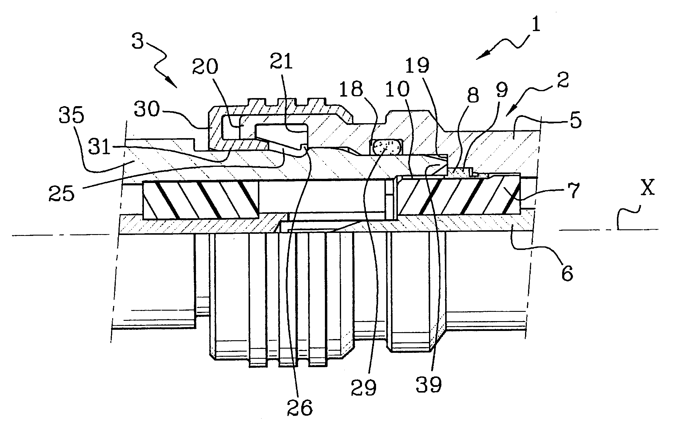
FIG. 1 shows a connector 1 of the invention comprising a first connector element given overall reference 2 and arranged in the example described as a male plug, together with a second connector element given overall reference 3 and arranged as a female receptacle.

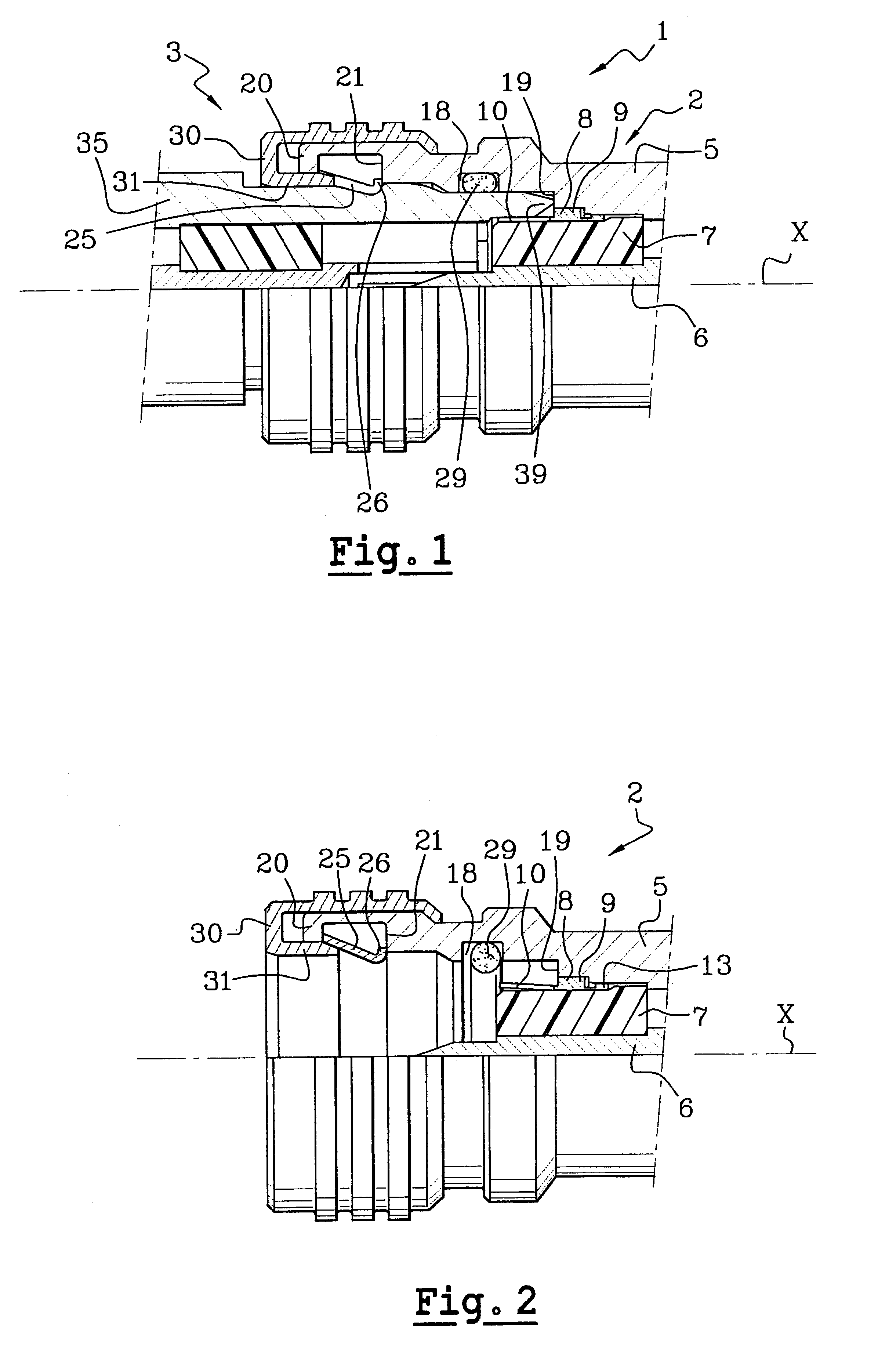
The first connector element 2 shown in isolation in FIG. 2 comprises a conductive body 5 that is circularly symmetrical about an axis X that forms a ground contact, a central contact 6, and insulation 7 in which the central contact 6 is held.

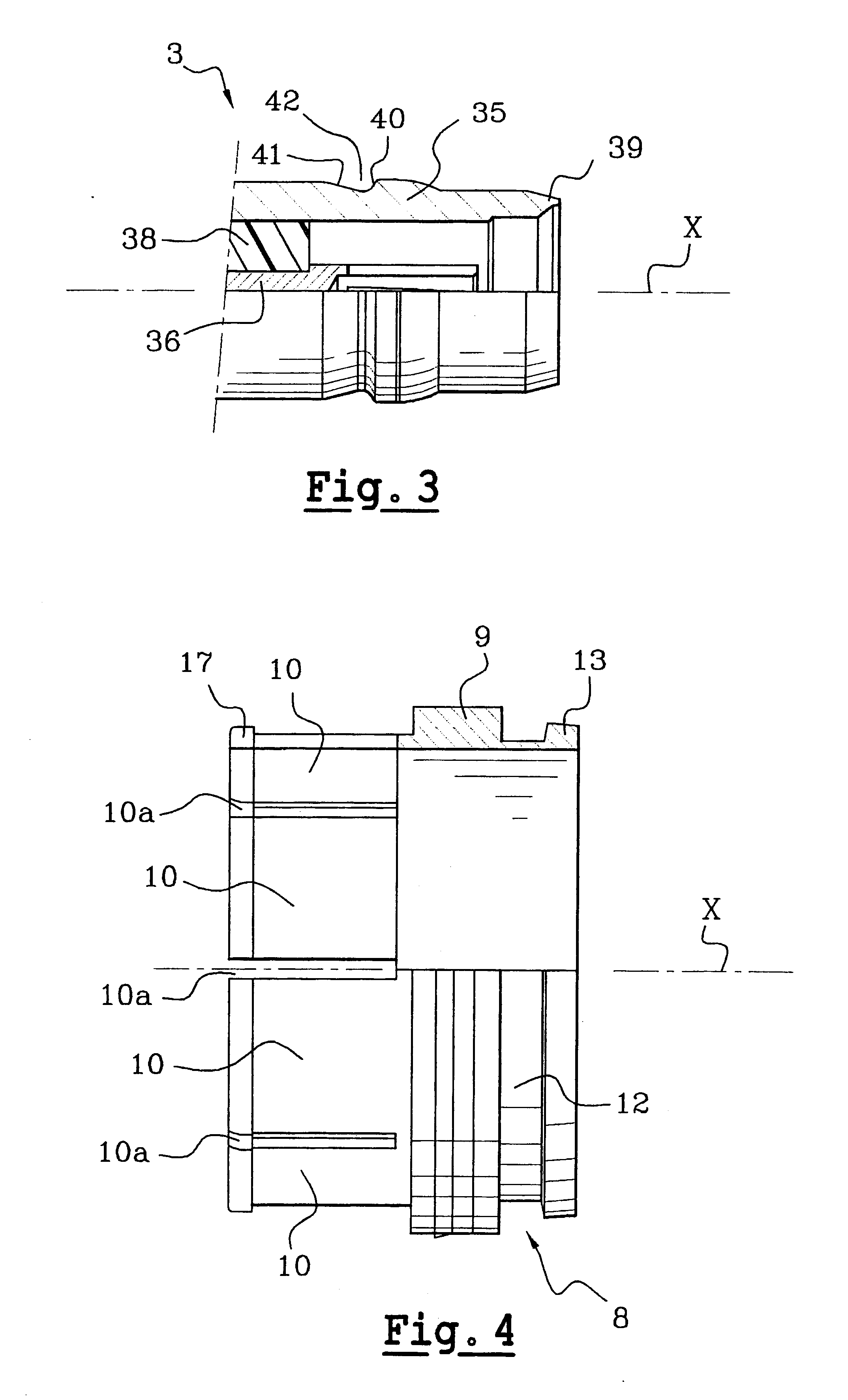
The insulation 7 is inserted in a member 8 forming an internal ground contact that comprises a central annular ring 9 having connected to one end thereof a plurality of elastically deformable tabs 10 and to the other end thereof an extension 12 extending rearwards and presenting at its free end an annular bead 13, as can be seen in particular in FIG. 4.

The free ends of the tabs 10 together define an annular bead 17.

The member 8 is inserted by force into the cavity in the tubular body 5,...


PUM


Abstract

A coaxial connector with locking by snap-fastening, the connector comprising two complementary connector elements each comprising a tubular body forming a ground contact and containing a central contact, which central contact is male in one of the bodies and female in the other and is held in the corresponding body by means of insulation, wherein a first one of the connector elements has a retaining member suitable for exerting a radial force on the second connection element which is arranged in such a manner that said radial force generates an axial force on the second connector element tending to press it axially against a bearing surface of the first connector element, and wherein the body of one of the connector elements has a member inserted therein that forms an internal ground contact and that is suitable for coming into contact with an inner wall of the body of the other connector element while exerting relatively strong contact pressure thereagainst.

Description

The present invention relates to a coaxial connector with locking by snap-fastening.European patent application EP 1 094 565 describes a coaxial connector comprising a connector element and a complementary connector element. The connector element has a sleeve carrying snap-fastening tabs whose free ends present respective shoulders suitable for coming into abutment against a sloping surface of the complementary connector element in such a manner as to exert an axial force thereon. That connector is satisfactory in terms of leakage at microwave frequencies, but relatively high levels of interfering frequencies appear in that connector due to the phenomenon of intermodulation, and that is unacceptable, particularly in the field of telecommunications where microwave signals are being transmitted to an antenna or from an antenna.OBJECTS AND SUMMARY OF THE INVENTIONThere exists a need for coaxial connectors that present a high level of shielding against leakage in the microwave range, si...

Claims


Application Information

Patent Timeline
Patent Type & Authority Patents(United States)
IPC IPC(8): H01R13/627H01R13/646
CPCH01R13/6277H01R2103/00H01R24/40H01R4/48
Inventor SCHNEIDER, MARIOGUIDET, OLIVIER
Owner RADIALL SA
Learn More