
Monitoring fluid flow in a pressure support system

a technology of pressure support system and monitoring system, which is applied in the direction of valves, respirators, mechanical equipment, etc., can solve the problems of increasing the complexity and increasing the cost of the device, and relatively inaccurate monitoring technique, etc., and is not suitable for quantitatively measuring the flow or volume of gas

Inactive Publication Date: 2003-11-11
RIC INVESTMENTS LLC
View PDF16 Cites 114 Cited by
  • Summary
  • Abstract
  • Description
  • Claims
  • Application Information

AI Technical Summary

Problems solved by technology

It can be appreciated that providing a conventional flow sensor in the pressure support system increases the complexity and cost of the device.
This monitoring technique, however, is relatively inaccurate, and, therefore, not suitable for quantitatively measuring the flow or volume of gas in the pressure support system, which is especially important in using the measured flow for triggering and cycling purposes.

Method used


Image

  • Monitoring fluid flow in a pressure support system
  • Monitoring fluid flow in a pressure support system
  • Monitoring fluid flow in a pressure support system

Examples


Embodiment Construction

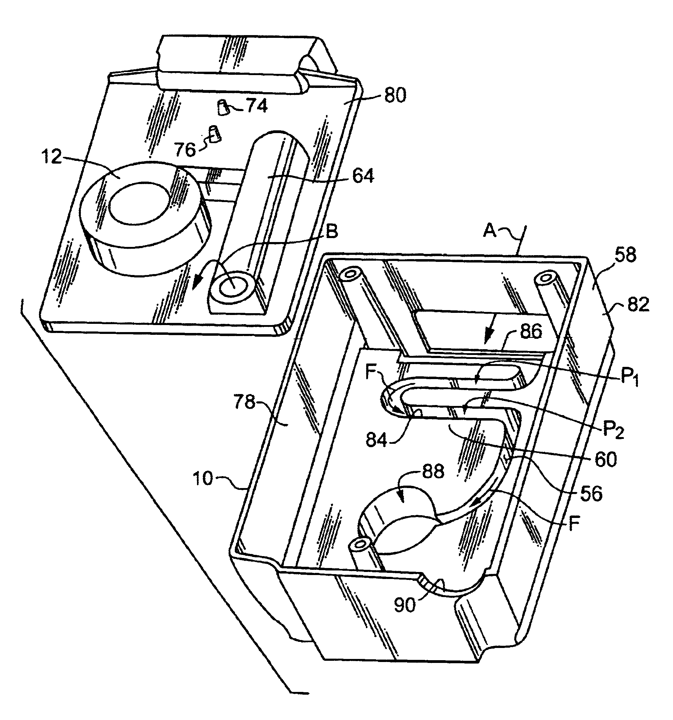
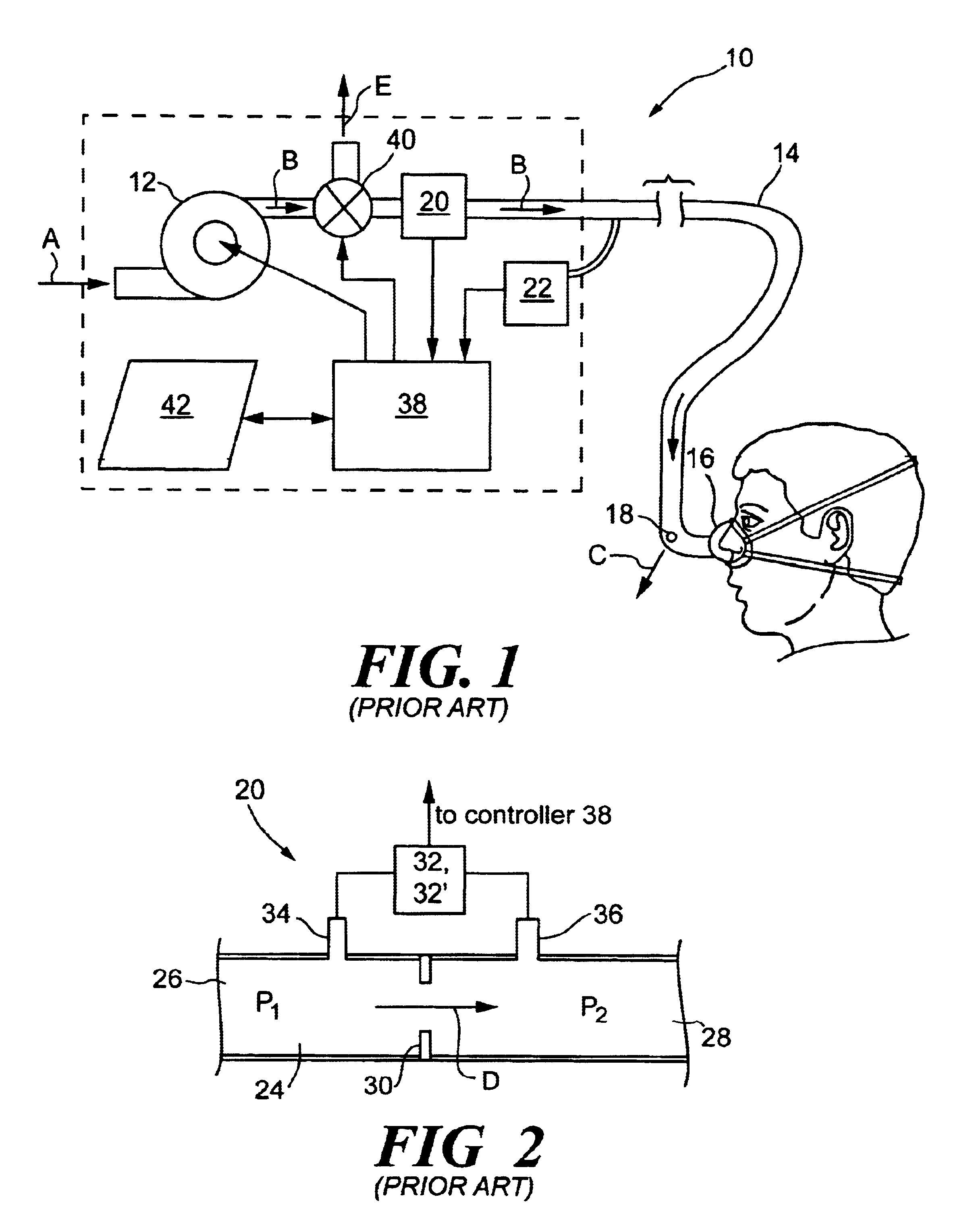
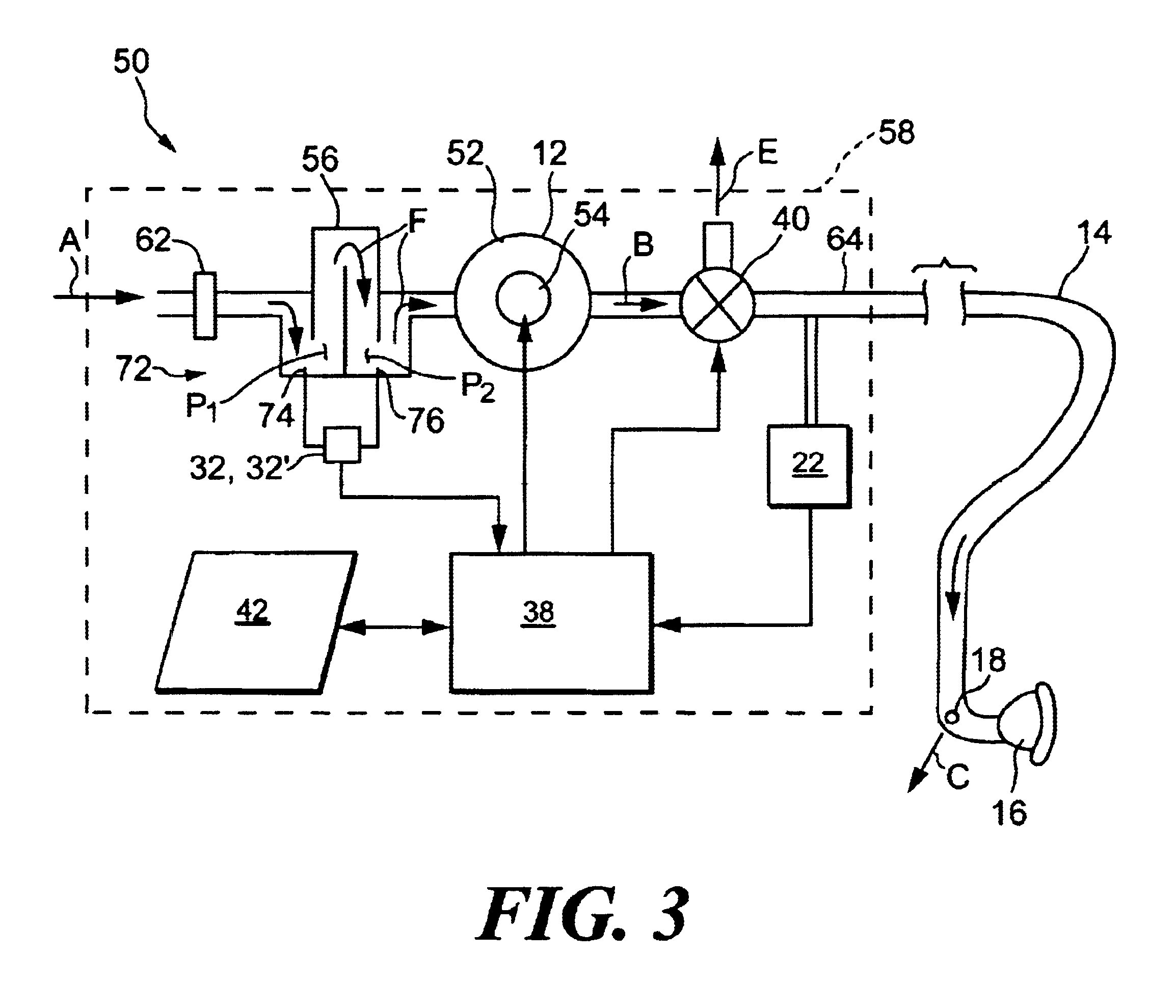
A pressure support system 50, according to the principles of the present invention, will now be described with reference to FIGS. 3-5. For simplicity of description, like elements in the description of the present invention shown in FIGS. 3-5 and in the description of the conventional pressure support system shown in FIG. 1 have like reference numbers.

Pressure support system 50 includes a pressure generator 12 in the form of a blower assembly 52 driven by a motor 54. An inlet of the blower is coupled to a first conduit 56 that communicates the inlet of the blower to a source of breathing gas for the pressure generator, such as ambient atmosphere. It is to be understood that other sources of gas can be used instead of, or in addition to, the air from the ambient atmosphere. For example, a supply of oxygen or an oxygen mixture can be provided as source of breathing gas. In addition, other types of pressure generators, such as a piston, bellows, or fan, can be provided for pressure gen...


PUM


Abstract

The present invention pertains to a pressure support system in which a flow or volume of gas is measured without using a dedicated flow element used in a conventional flow meter. Instead, the present invention provides a tortuous gas flow path in which a pressure differential is created between two points in the tortuous path. This pressure differential created by the gas flow path provides the necessary pressure drop for measuring the gas flow and / or gas volume passing through the pressure support system.

Description

1. Field of the InventionThe present invention pertains to a technique for measuring gas flow and / or volume in a pressure support system, and, more particularly, to a gas flow and / or volume measurement technique in which a pressure differential occurring between two points in a tortuous gas flow path in the pressure support system is used to measure the gas flow and / or gas volume passing through the tortuous gas flow path, thereby eliminating the need for a dedicated flow element in the gas flow path to create the pressure differential for flow / volume measurement purposes.2. Description of the Related ArtPressure support systems that provide a flow of gas to an airway of a patient at an elevated pressure via a patient circuit to treat a medical disorder are well known. For example, it is known to use a continuous positive airway pressure (CPAP) device to supply a constant positive pressure to the airway of a patient to treat obstructive sleep apnea (OSA) as well as other disorders. ...

Claims


Application Information

Patent Timeline
Patent Type & Authority Patents(United States)
IPC IPC(8): A61M16/00
CPCA61M16/00A61M16/0069A61M2016/0021A61M2205/12A61M2205/42A61M2016/0039A61M16/107A61M2016/0027A61M16/0858A61M16/024
Inventor TRUITT, PATRICK W.DUFF, WINSLOW K.
Owner RIC INVESTMENTS LLC
Learn More