
Asynchronous fluorescence scan

Inactive Publication Date: 2003-10-28
CERCACOR LAB INC
View PDF4 Cites 687 Cited by
  • Summary
  • Abstract
  • Description
  • Claims
  • Application Information

AI Technical Summary

Problems solved by technology

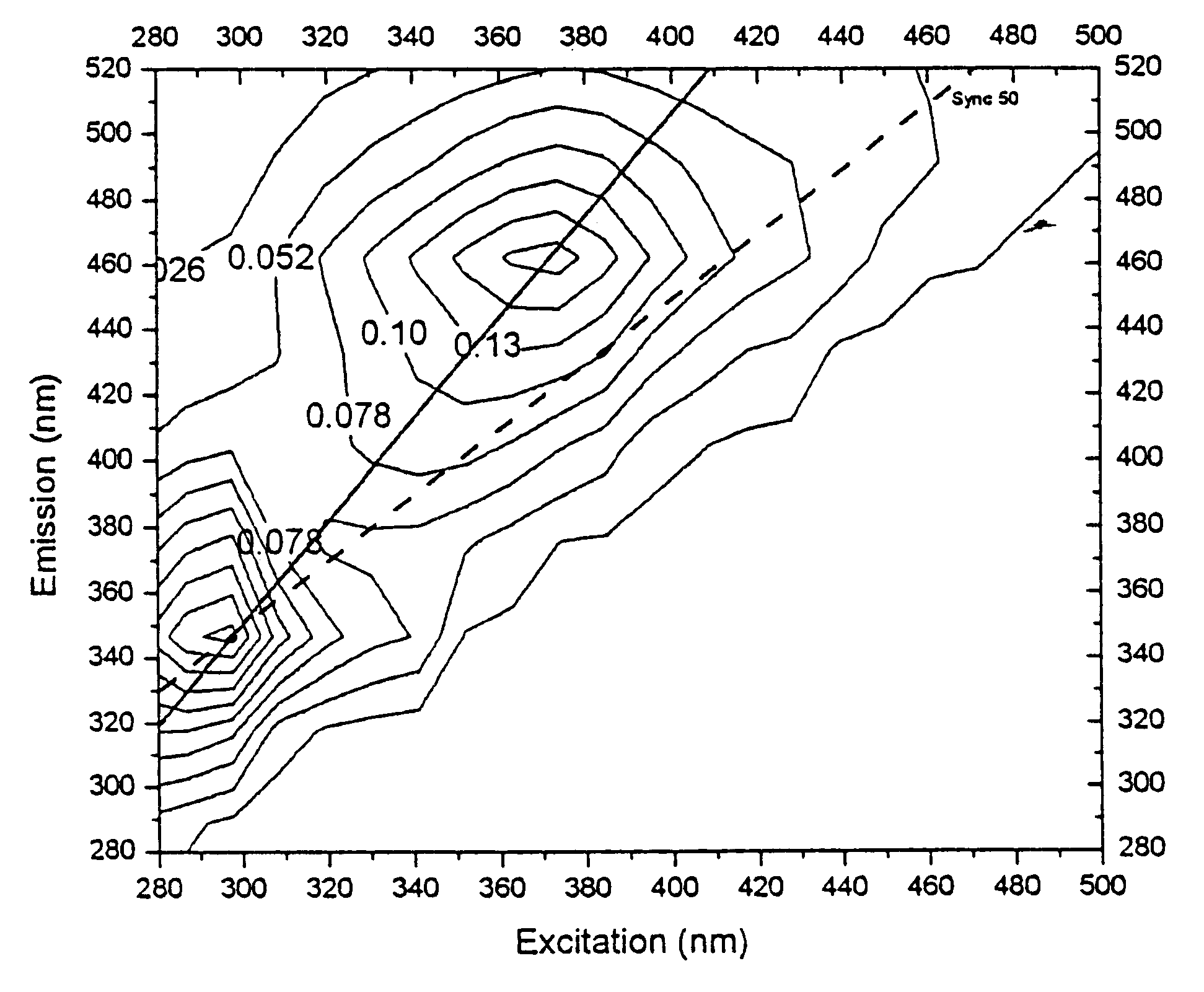
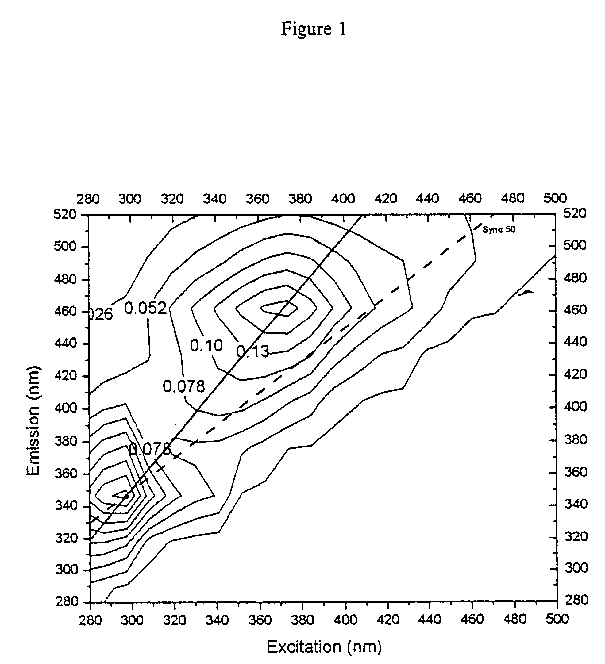
However, fluorescent data which can be collected from such instruments are limited to spectra whose optimal collection wavelengths vary by the set constant with respect to the wavelength of the excitation radiation.

Method used


Image

  • Asynchronous fluorescence scan
  • Asynchronous fluorescence scan
  • Asynchronous fluorescence scan

Examples


Embodiment Construction

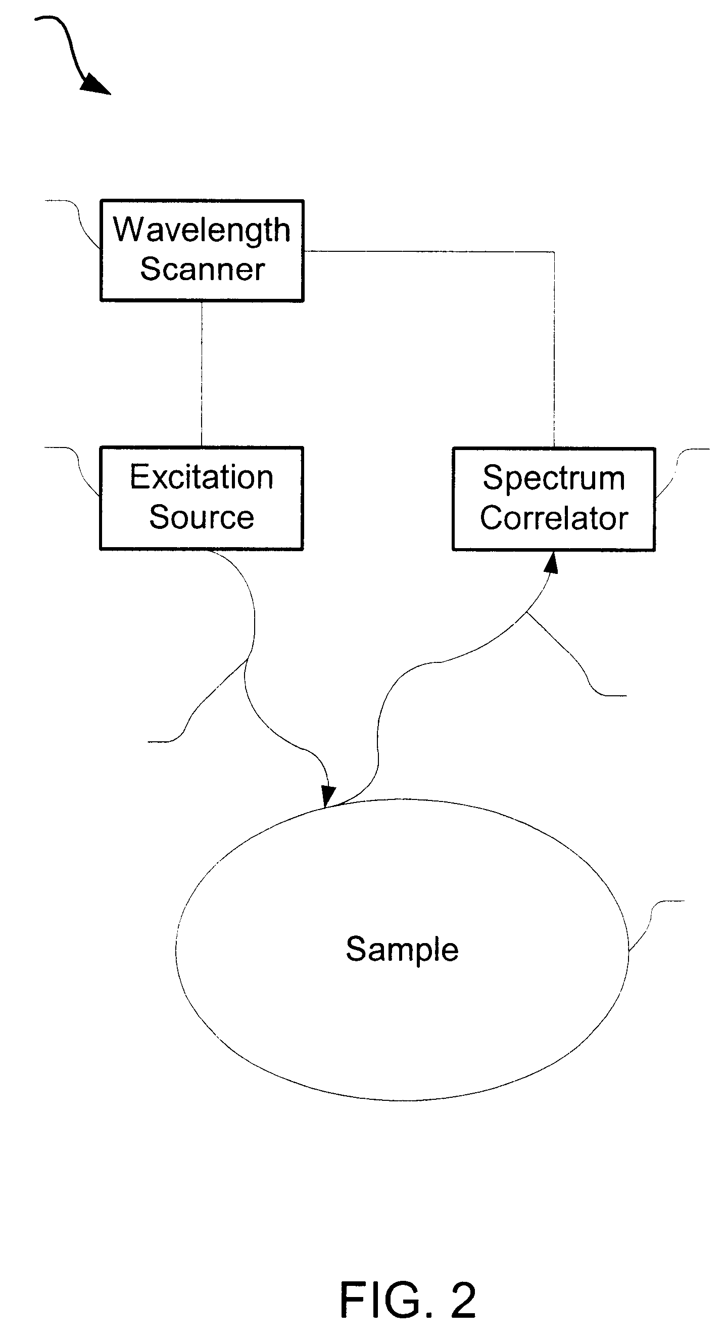
As embodied and broadly described herein, the present invention is directed to the collection of fluorescence spectra using an asynchronous fluorescence scan. More specifically, the present invention relates to the use of asynchronous fluorescence scanning to obtain fluorescence data from a sample, such as skin, mucous membranes or other tissue, or a biological fluid such as blood or serum, in connection with chemical analysis, biomedical diagnostics, or other evaluation or analysis of the status of the sample. The present invention may be used in human and veterinary medical applications, forensic applications, as well as any other application where fluorescence may be used to determine or analyze the composition, contents, or other features of a sample.

Unlike conventional synchronous scans in which .DELTA..lambda. is maintained as a constant, the present invention allows .DELTA..lambda. to vary during the scan according to the equation .lambda..sub.em =.lambda..sub.ex +.DELTA..lam...


PUM


Abstract

The present invention is directed to asynchronous scanning devices and methods of using asynchronous scanning to acquire fluorescence data from a sample, such as biological tissue, to facilitate diagnosis of the presence or absence of disease or other abnormality in the sample. The present invention is useful for biomedical diagnostics, chemical analysis or other evaluation of the target sample.

Description

1. Field of the InventionThis invention relates to devices useful for the acquisition of fluorescence data from a sample, such as biological tissue, in order to analyze the status or composition of the sample, and, in particular, to devices and methods that utilize asynchronous fluorescence scanning to assess the presence or absence of pathology in skin or other tissue.2. Description of BackgroundFluorescence, by definition, involves the excitation of a fluorophore by light of a given wavelength, .lambda..sub.ex. The fluorophore then re-emits light at a lower energy, and hence a longer wavelength, .lambda..sub.em. Thus, .lambda..sub.em is always greater than .lambda..sub.ex for fluorescence. In addition, the amount of emitted fluorescent light is typically much less than the excitation light, and therefore instrumental limitations (e.g., band pass width, straylight rejection) force a minimum separation .DELTA..lambda..sub.min between the more intense excitation wavelength .lambda..s...

Claims


Application Information

Patent Timeline
IPC IPC(8): A61B5/00G01N21/64
CPCA61B5/0059A61B5/441G01N21/6486A61B5/14532G01N2021/6421G01N2021/6417G01N2021/6419G01N21/6456
Inventor TREPAGNIER, PIERRE
Owner CERCACOR LAB INC
Learn More