
Diagnostic golf club system

a golf club and golf technology, applied in golf clubs, golf accessories, racket sports, etc., can solve the problems of not every golfer having ready access to professional golf instruction, obstructive, and cumbersome wires

Inactive Publication Date: 2003-10-28
TOPGOLF CALLAWAY BRANDS CORP
View PDF61 Cites 120 Cited by
  • Summary
  • Abstract
  • Description
  • Claims
  • Application Information

AI Technical Summary

Benefits of technology

It is a further object of the present invention to provide an instrumented golf club with non-volatile memory so that the memory is not lost if the club is turned off or the battery is removed.
It is a further object of the present invention to provide an instrumented golf club capable of converting a series of strain measurements to a series of force and bending moments in order to generate a shaft flex profile for a golfer.

Problems solved by technology

However, not every golfer has ready access to professional golf instruction.
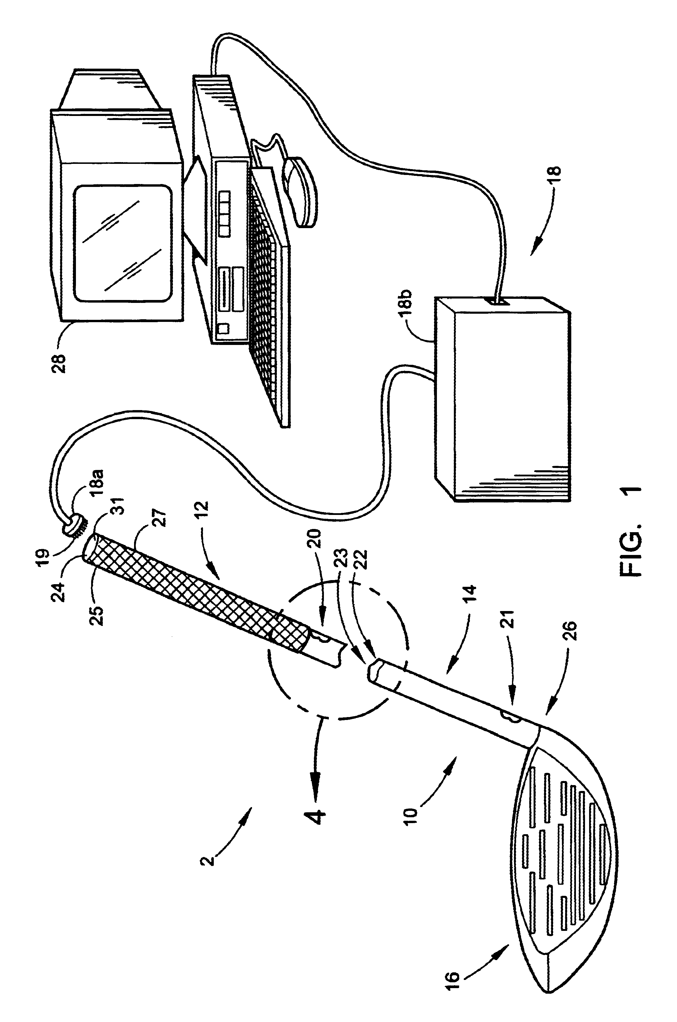
A significant drawback associated with the use of wires in an instrumented golf club is that the wires can be very cumbersome, and can become obtrusive to the golfer when the golfer attempts to swing the golf club.
However, this bat does not contain any data storage capability.
Thus, data transfer to an external memory device is a significant drawback.
The cumbersome nature of data transfer via cables or wires affects the motion and feel of a golfer's actual golf swing.
In addition, while the use of radio transmissions is preferable to the use of wires or cables emanating from the golf club for transferring data, a transmitter adds excessive weight.
The effective range of these wireless instrumented golf clubs is limited by the low power used in such embodiments, and the accuracy of the radio transmitted data is subject to interference or noise from other sources of nearby radio transmissions.
Furthermore, in conventional systems, the receiving equipment typically must be located in close proximity to the radio transmitter disposed in the golf club thereby restricting the flexibility and portability of using such systems.
Using a linear data capture approach, as taught by the prior art:, would require extensive amounts of memory, and would make it very difficult to provide such memory requirements completely internal to an instrumented golf club.

Method used


Image

  • Diagnostic golf club system
  • Diagnostic golf club system
  • Diagnostic golf club system

Examples


Embodiment Construction

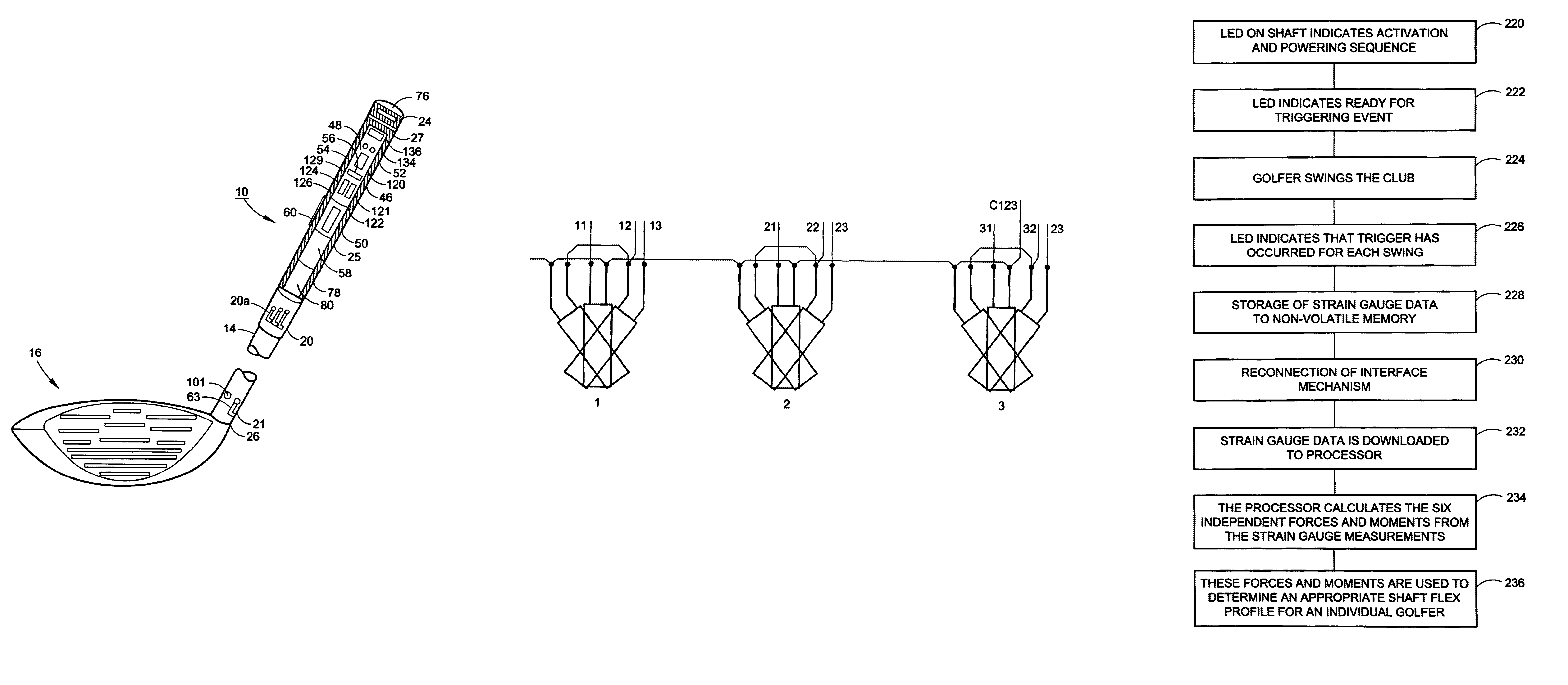
FIG. 5 is a view of an individual strain gauge group 20a as arranged about the circumference of the exterior of the shaft 14 of the instrumented golf club 10 of the present invention. Six independent strain gauge elements are needed to make essential measurements in order to calculate the six independent forces and moments. These six individual elements are axial force (Px), transverse shear forces (Vy) and (Vz), bending moments (My) and (Mz) and torsion (Tx). FIG. 6 is a view of these forces acting upon a typical strain gauge of the present invention.

Data obtained from the independent forces and moments acting on the shaft at the tip end 26 and butt end 27 are computed from the strain data received via the sets of strain gauges and from the information obtained relative to the shaft stiffness matrix at each location. These stiffness matrices are obtained using experimental or analytical techniques well known in the art. Once obtained, the values are entered into the computer progra...


PUM


Abstract

A diagnostic golf club system having a diagnostic golf club, an interface means and a computing means is disclosed herein. The diagnostic golf club includes a plurality of strain gauges, an internal power supply, and a non-volatile memory for capturing data relating to a golf swing. The interface means is capable of transferring data from the diagnostic golf club to the computing means for processing the data and presenting the data in a useful and informative format. The data may be used to determine a shaft flex profile for a particular golfer.

Description

Not Applicable1. Field of the InventionThe present invention relates to golf equipment and, more specifically, to a diagnostic golf club having the ability to make quantitative measurements of specific mechanical or physical properties of the golf club during a golf swing. Strain gauges are provided on the exterior of the shaft of the golf club and a memory device is provided within the interior containing data descriptive of the measured properties.2. Description of the Related ArtVarious data measuring and collecting devices and methods are used for analyzing a golf club during a golf swing. In a similar manner, the effectiveness of a golf ball impact with the golf club during the golf swing can be measured in terms of initial launch conditions. Such launch conditions include the initial velocity, launch angle, spin rate and spin axis of the golf ball. These launch conditions are determined principally by the velocity of a club head at impact and the loft and angle of a club face ...

Claims


Application Information

Patent Timeline
Patent Type & Authority Patents(United States)
IPC IPC(8): A63B24/00A63B59/00A63B69/36A63B69/00A63B71/06
CPCA63B24/0003A63B59/0074A63B69/3614A63B69/3632A63B71/0619A63B71/0622A63B2225/50A63B53/12A63B59/0014A63B69/0002A63B2059/0003A63B2069/362A63B2220/24A63B2220/34A63B2220/35A63B2220/40A63B2220/51A63B2220/54A63B2220/62A63B2220/806A63B2220/807A63B2220/833A63B53/10A63B60/10A63B60/06A63B60/08A63B60/42A63B69/362A63B60/002
Inventor LEE, NATHAN J.LINSDAU, AARONHOUSHAR, JAN N.SIMMONS, NIGELMATTHEWSON, PETERANSELL, IAN
Owner TOPGOLF CALLAWAY BRANDS CORP
Learn More