Mixer assembly

a technology of mixers and components, applied in the direction of mixers, other chemical processes, mixing, etc., can solve the problems of small product flung, waste of product, and mess for workmen, and achieve the effect of preserving product and minimizing the amount of mess created

Inactive Publication Date: 2003-10-21
FRENCH RONALD +1
View PDF15 Cites 9 Cited by
  • Summary
  • Abstract
  • Description
  • Claims
  • Application Information

AI Technical Summary

Benefits of technology

The mixer assembly of the present invention is utilized with the conventional stirrer assembly having an elongated driven shaft and an agitator mounted at one end of the shaft. With the agitator positioned within the interior of the container, the cover is detachably secured across the open top of the container so that the stirrer assembly shaft protrudes through the conduit so that the free end of the shaft is positioned above the cover. A rotary drive, such as a drill, is then secured to the upper free end of the shaft so that, upon activation of the rotary drive, the agitator is rotatably driven thus mixing the product within the container. Furthermore, the diameter of the conduit is preferably several times the diameter of the drive shaft so that the drive shaft can be skewed relative to the conduit to enable complete mixing of the product within the container.
A primary advantage of the mixer assembly of the present invention is that the cover and conduit prevents the product from being flung or expelled from the container during the mixing process. This not only conserves product, but also minimizes the amount of mess created during the mixing process.

Problems solved by technology

One disadvantage of this previously known method for stirring such commercial product is that, with the cover removed, a small portion of the product is flung from the container by the agitator during the stirring process.
This not only wastes product, but also creates a mess for the workman.

Method used


Image

  • Mixer assembly
  • Mixer assembly
  • Mixer assembly

Examples


Embodiment Construction

With reference first to FIG. 1, a container 10 of the type utilized to contain commercial product, such as roofing sealant, plaster, paint, cementitious material or the like, is shown. The container 10 includes a closed and generally circular sidewall 12 and a closed bottom 14. The container 10 has an upper rim 16 which forms an open top for the container 10. The container 10, furthermore, is of the type used for commercial products and, as such, is typically five or ten gallons in size.

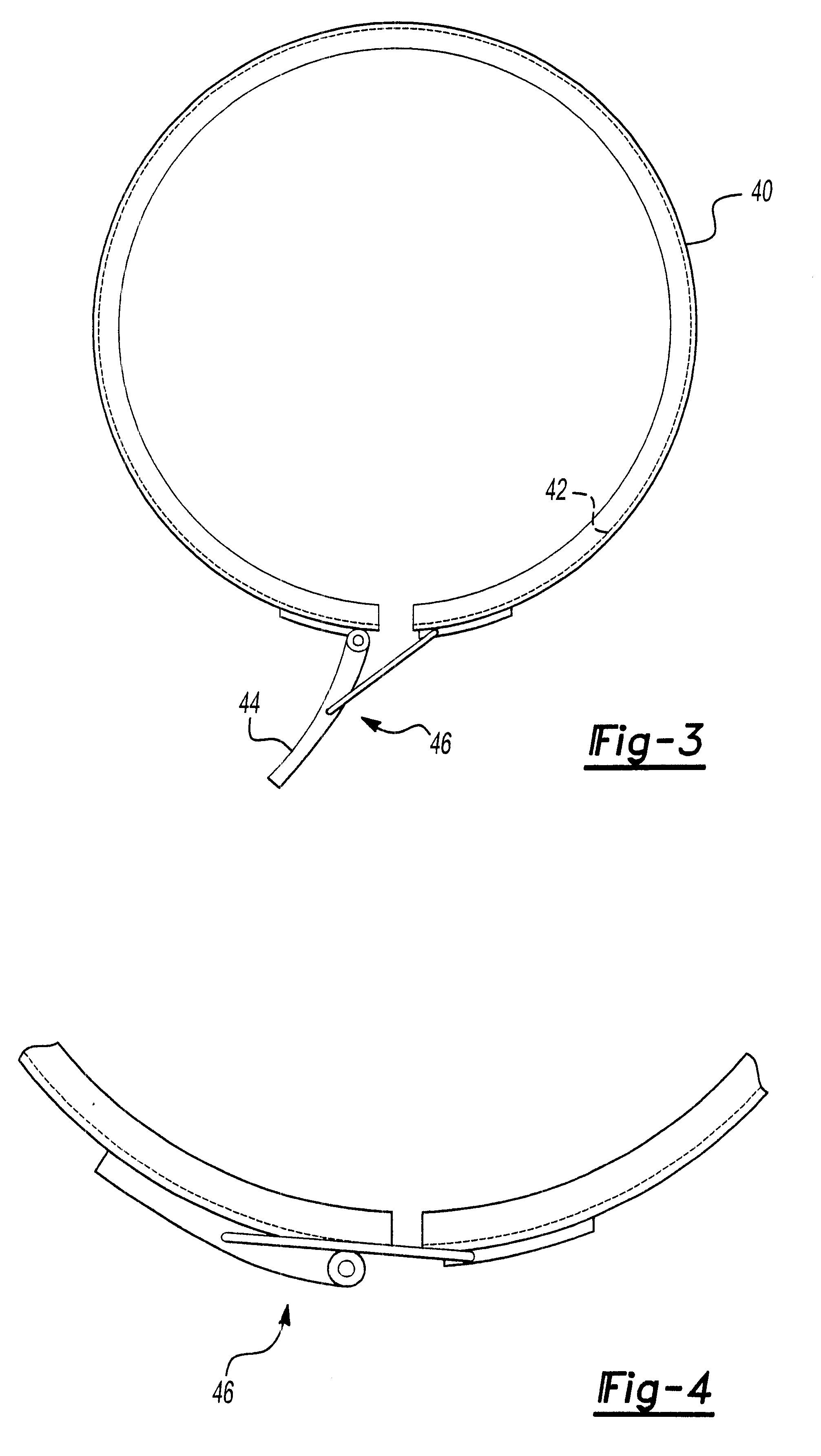
With reference now to FIGS. 1 and 2, the mixer assembly of the present invention includes a generally circular cover 20 dimensioned to overlie and cover the open top of the container 10. The cover 20 thus includes an outer rim 22 which is dimensioned to fit over and receive the upper rim 16 of the container 10.

Referring now particularly to FIG. 2, the cover 20 includes a through opening 24 which is preferably centrally located on the cover 20. A tubular conduit 26 is then detachably secured to the co...


PUM


Abstract

A mixer assembly is disclosed having a container with a closed sidewall, a closed bottom and a rim which forms an open top. The container is adapted to contain a product, such as roofing sealant, plaster or the like, to be mixed. A cover overlies the open top while a clamp detachably secures the cover to the container rim. A tubular conduit is attached to the cover so that the opposite ends of the conduit are open to the opposite sides of the cover. A stirrer assembly having a driven shaft and an agitator secured to one end of the shaft is then positioned within the container so that the agitator is solely contained within the container while the shaft extends exteriorly through the conduit and above the cover. A rotary drive, such as a drill, is then secured to the upper end of the shaft to rotatably drive the agitator and mix the product within the container.

Description

I. Field of the InventionThe present invention relates generally to mixer assemblies.II. Description of the Prior ArtMany types of commercial product, such as plaster, roofing sealant, paint, cementitious material and the like, are typically sold in containers having a closed sidewall, a closed bottom and an upper rim which forms an open top. A cover is then detachably secured to the container rim, which enables shipment of the product.When use of the product is desired, the cover is typically removed and, in many cases, the product must be stirred prior to use. Conventionally, a stirrer assembly having an elongated shaft with an agitator at one end is used to stir the product. With the top removed, the agitator is positioned within the interior of the container while a rotary drive, such as a drill, is secured to the free end of the drive shaft. As the agitator is rotatably driven by the rotary drive, the product within the container is mixed as desired.One disadvantage of this pre...

Claims


Application Information

Patent Timeline
Patent Type & Authority Patents(United States)
IPC IPC(8): B01F13/00
CPCB01F13/002B01F15/00006Y10S366/605B01F33/5011B01F33/86
Inventor FRENCH, RONALDFRENCH, RICHARD
Owner FRENCH RONALD
Why Eureka
Try Eureka