
Procedure and system for the transmission of information and establishment of a telecommunication connection

Inactive Publication Date: 2003-09-30
HANGER SOLUTIONS LLC +1
View PDF12 Cites 21 Cited by
  • Summary
  • Abstract
  • Description
  • Claims
  • Application Information

AI Technical Summary

Benefits of technology

It is accordingly the desideratum of the present invention to eliminate, or at least significantly reduce, the drawbacks and deficiencies of the prior art, as for example described hereinabove.
The present invention thus allows optimal routing to the mobile switching center under which the B-subscriber is then or currently located. If, according to the data in the visitor location register, the subscriber cannot be reached, then corresponding information is obtained. If the subscriber has transferred his or her calls to another number using the CFU (Call Forwarding Unconditional) supplementary service, this too will be known so that the call can be properly routed to the specified forward number.
As will be further appreciated, the inventive solution advantageously does not require any changes in the elements of the mobile communication network or in the intelligent network because the invention implements the enhanced service through the use of a separate MAP-INAP base.

Problems solved by technology

The primary problem with the above-described routing procedure is that calls addressed to mobile stations are not automatically routed via the shortest route to the proper mobile switching center but may, instead, be routed via several switching centers.
Such solutions, however, disadvantageously they bind the service to a certain base and assume that the service control point or service node is provided with an MAP interface.

Method used


Image

  • Procedure and system for the transmission of information and establishment of a telecommunication connection
  • Procedure and system for the transmission of information and establishment of a telecommunication connection
  • Procedure and system for the transmission of information and establishment of a telecommunication connection

Examples


Embodiment Construction

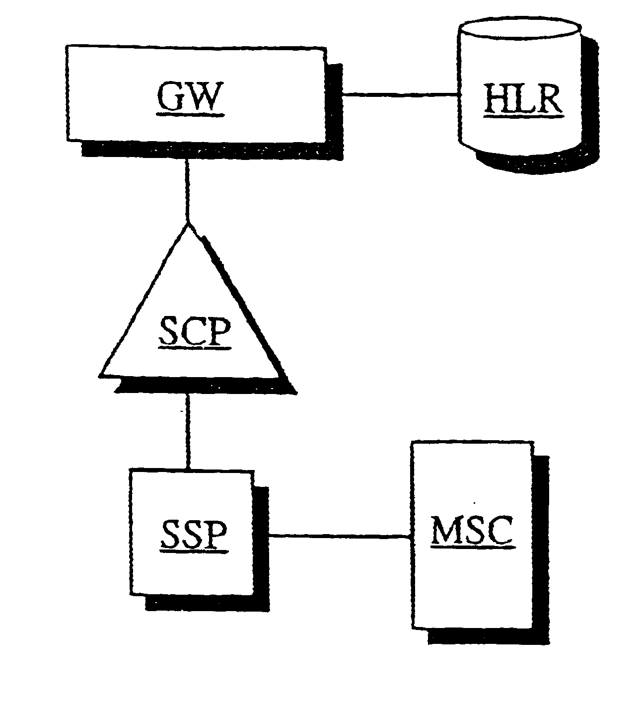
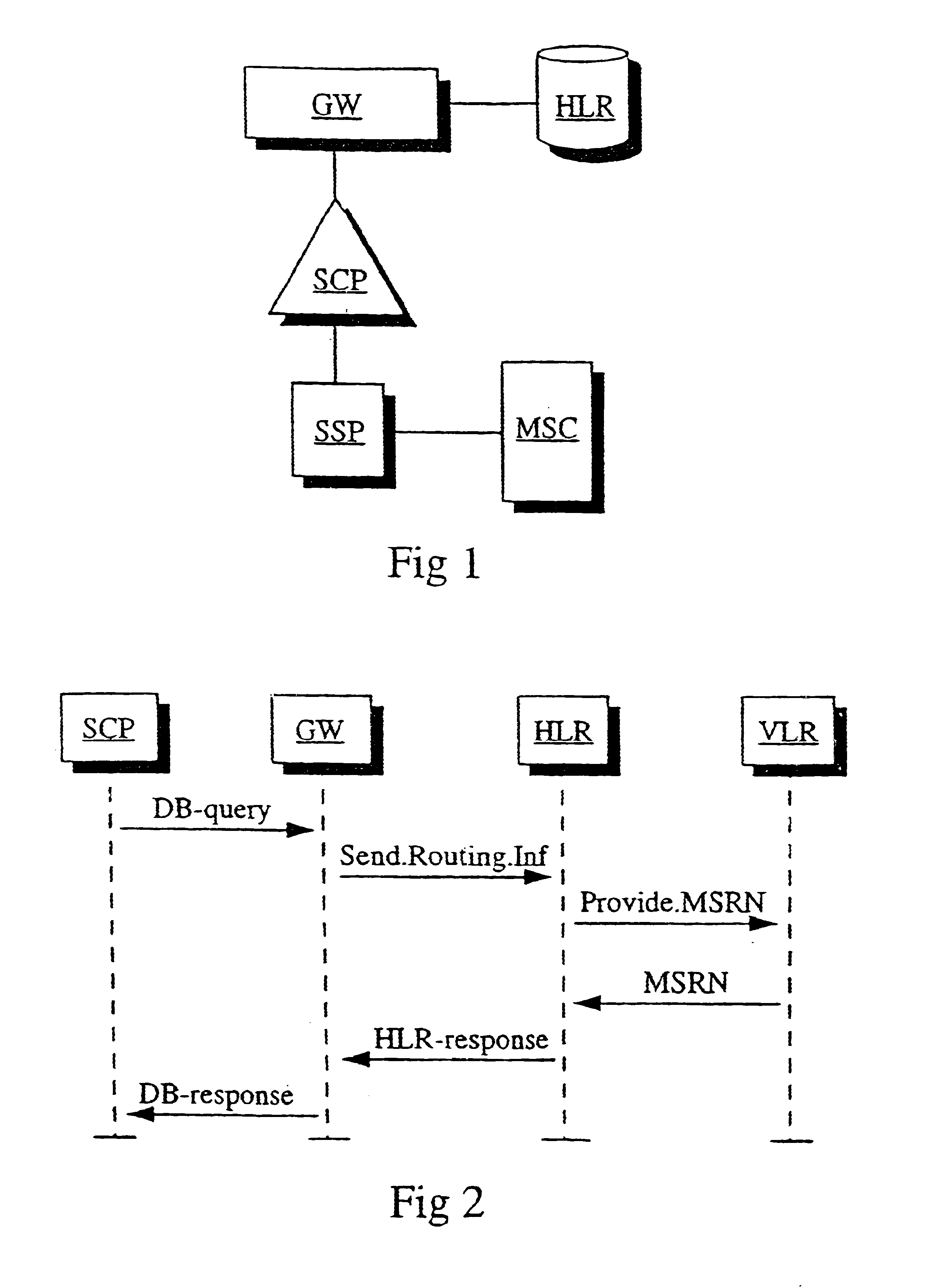
The system configured in accordance with the present invention and illustrated in FIG. 1 comprises a mobile switching center MSC and a service switching point SSP which is connected to a service control point SCP. In addition, the service control point SCP is connected to a gateway GW which, in turn, is also connected to a subscriber register HLR.

In the signaling diagram of FIG. 2, the system includes a service control point SCP, an MAP-INAP gateway GW, a home location register HLR, and a visitor location register (VLR).

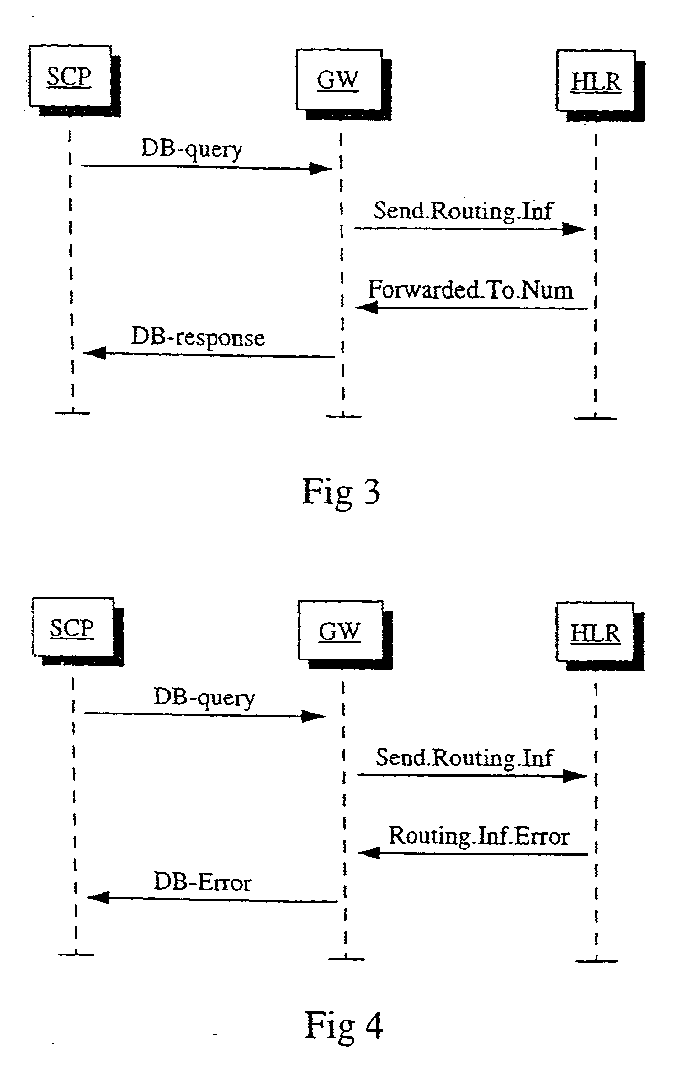
In the signaling diagram of FIG. 3, the system includes a service control point SCP, an MAP-INAP gateway 6W, and a home location register HLR. With initial reference to FIG. 1, an effort to establish a communication connection starts with a call setup request that is sent from the terminal device (not shown) of a calling or A-subscriber to the gateway mobile services switching center MSC. The gateway MSC detects the incoming call and further directs it to the service...


PUM


Abstract

Procedure and system for optimizing the route of a telecommunication connection to be set up in a telecommunication system that includes a mobile switching center (MSC), a service switching point (SSP), a service control point (SCP), a gateway (GW), and a subscriber register (HLR). The service switching point is connected to the service control point and the gateway is connected to the service control point and to the subscriber register. The telecommunication connection to be set up is directed via the service switching point to the service control point. A database query is sent from the service control point, via the gateway, to the subscriber register. In response, the subscriber register returns routing information, on the basis of which an optimal route to the mobile switching center under which the B-subscriber is currently located is determined.

Description

1. Field of the InventionThe present invention relates to telecommunication technology and, more particularly, the invention is directed to optimization of the route of a telecommunication connection that is set up in a mobile communication network.2. Description of Related ArtFor a teleoperator, i.e. an owner or operator of a telecommunications network, it is important that telecommunication connections be set up in an optimal manner. Optimization may for example be based on the length of the route of the connection or on the network load resulting from the connection. Because the traffic in mobile communication networks is continuously increasing, it is particularly important that the load in such networks remain as low as possible. One approach to reducing the load in a mobile communication network is to set up or establish the connection to the mobile switching center then serving the called subscriber via a route that is as short as possible.An intelligent network is formed by ...

Claims


Application Information

Patent Timeline
IPC IPC(8): H04Q3/00H04Q7/38H04W8/08
CPCH04Q3/0045H04W8/082
Inventor GROHN, TUOMOPERA, OLLIALA-LUUKKO, SAMISARKKI, MIKA
Owner HANGER SOLUTIONS LLC
Learn More