
Received power calculating method and mobile station

a technology of receiving power and calculation method, which is applied in the field of mobile communication system, can solve the problems of increasing the power of received interference of other subscribers, deteriorating the bit error rate of received signals, and affecting the transmission of signals

Inactive Publication Date: 2003-09-30
NEC CORP
View PDF8 Cites 134 Cited by
  • Summary
  • Abstract
  • Description
  • Claims
  • Application Information

AI Technical Summary

Problems solved by technology

Thus, the bit error rate of the received signal deteriorates.
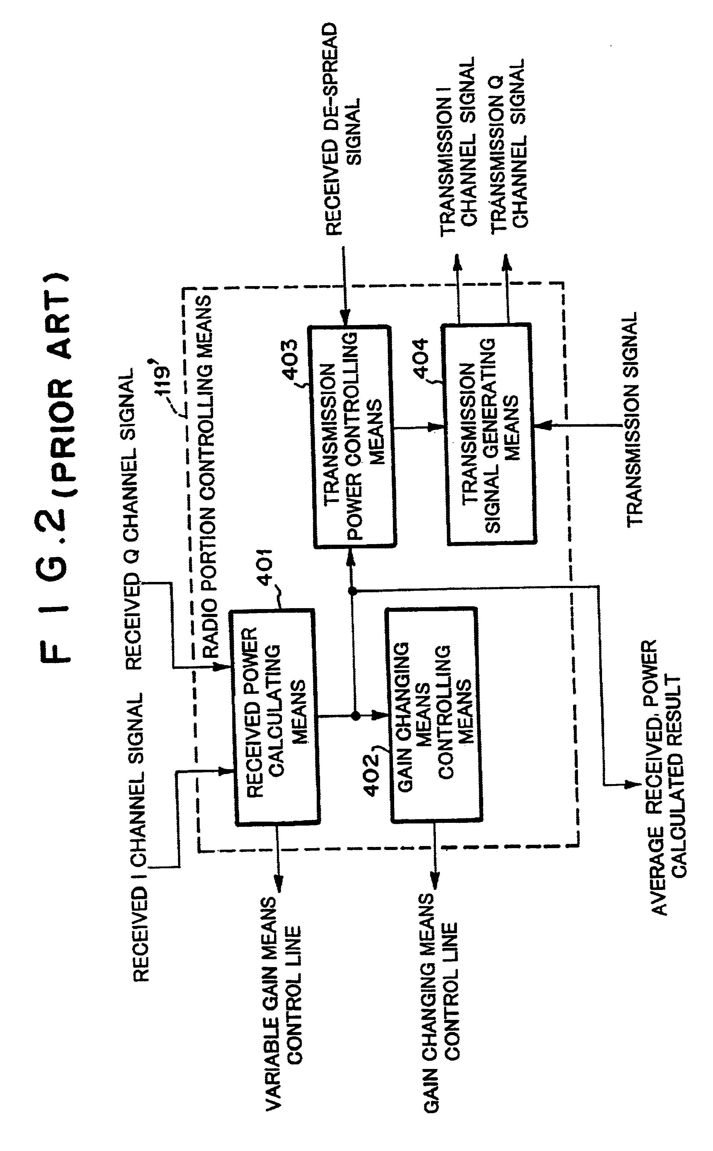
When the received power at the end of the antenna becomes large and thereby the gain of the gain changing means varies, if the timing at which the gain is changed does not match the timing at which the gain of the variable gain means is varied, the calculated value of the average received power has an error such as a phase error.
Consequently, when the incorrect transmission power control signal causes the base station to increase the transmission power, the received interference powers of other subscribers increase and thereby bit error rate of other subscribers deteriorates.
In addition, when the base station decreases the transmission power due to an incorrect transmission power control signal, the local received interference power increases and thereby the local bit error rate deteriorates.

Method used


Image

  • Received power calculating method and mobile station
  • Received power calculating method and mobile station
  • Received power calculating method and mobile station

Examples


Embodiment Construction

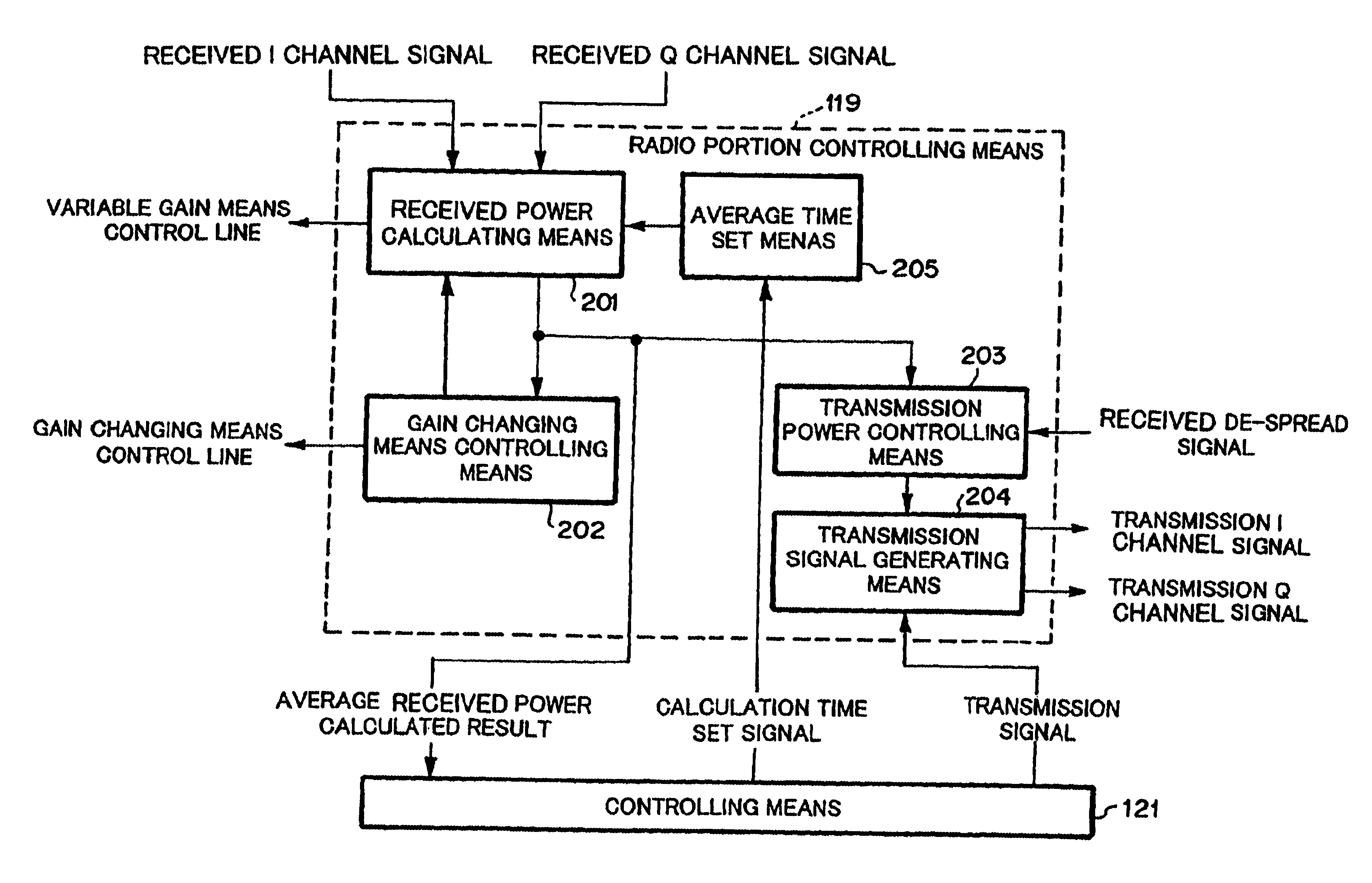
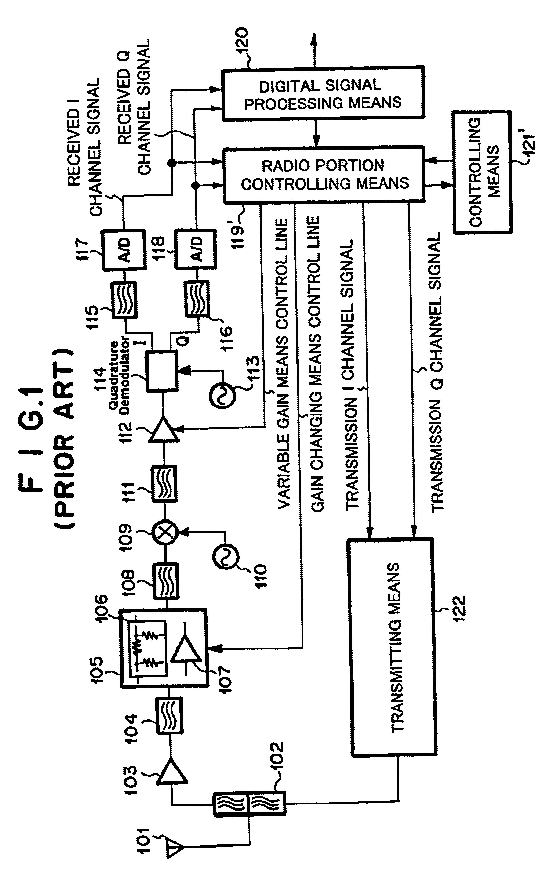
FIG. 3 is a block diagram showing the structure of a mobile station according to an embodiment of the present invention. FIG. 4 is a block diagram showing the structure of a radio portion controlling means according to the embodiment of the present invention.

Referring to FIG. 3, the mobile station has an antenna means 101, an duplexer means 102, a first radio frequency amplifying means 103, a first band pass filter means 104, a gain changing means 105, a second band pass filter means 108, a first local signal oscillating means 110, a frequency converting means 109, a channel filter means 111, a variable gain means 112, a second local signal oscillating means 113, an quadrature demodulating means 114, low pass filter means 115 and 116, A / D converting means 117 and 118, a radio portion controlling means 119, a digital signal processing means 120, a transmitting means 122, and a controlling means 121. The duplexer means 102 separates a transmission signal from a received signal. The ga...


PUM


Abstract

A radio portion controlling means of a receiver of a mobile station has an average time setting means. A controlling means supervises an average received power. When the average received power approaches a power at which the gain of a gain changing means should be changed, the controlling means causes a received power calculating means to increase the time period for the calculation of the average received power so as to decrease the error of the average received power at which the gain of the gain selecting means is changed.

Description

1. Field of the InventionThe present invention relates to a mobile communication system, in particular, to a received power calculating method of a receiver of a radio portion of a mobile communication system, the receiver calculating a received power and controlling a down-link transmission power of a base station.2. Description of the Related ArtIn the CDMA (Code Division Multiple Access) system, when a base station spreads a spectrum of a transmission signal with a plurality of predetermined codes and communicates with mobile stations using the spread signal, the same frequency band can be assigned to a plurality of subscribers or channels. Thus, frequencies can be effectively used. In the CDMA system, when a receiver receives a spread spectrum signal from the base station, unless the receiver de-spreads the spread spectrum signal with the same code at the same timing, the receiver cannot extract the original transmission signal. Thus, the bit error rate of the received signal de...

Claims


Application Information

Patent Timeline
Patent Type & Authority Patents(United States)
IPC IPC(8): H04B7/005H04B1/04H04B7/26H04W52/22H04W52/24H04W52/36H04W52/52
CPCH04W52/225H04W52/24H04W52/36H04W52/52
Inventor TAKAKI, TETSUYA
Owner NEC CORP
Learn More