
Method for converting a plurality of signals from one of a digital and analogue form to the other form

a plurality of signals technology, applied in the field of converting a plurality of signals from one of a digital and analogue form to the other form, can solve the problems of increasing the pin count of the integrated circuit, requiring relatively complex analogue reconstruction filters, and requiring active components which are relatively complex, and thus expensiv

Inactive Publication Date: 2003-09-16
ANALOG DEVICES INC
View PDF10 Cites 13 Cited by
  • Summary
  • Abstract
  • Description
  • Claims
  • Application Information

AI Technical Summary

Problems solved by technology

This significantly increases the pin count of the integrated circuit.
Alternatively, relatively complex analogue reconstruction filters are required in which the band pass of the filters can be varied for accommodating the video signals of different formats.
Such filters require active components which are relatively complex and thus expensive.

Method used


Image

  • Method for converting a plurality of signals from one of a digital and analogue form to the other form
  • Method for converting a plurality of signals from one of a digital and analogue form to the other form
  • Method for converting a plurality of signals from one of a digital and analogue form to the other form

Examples


Embodiment Construction

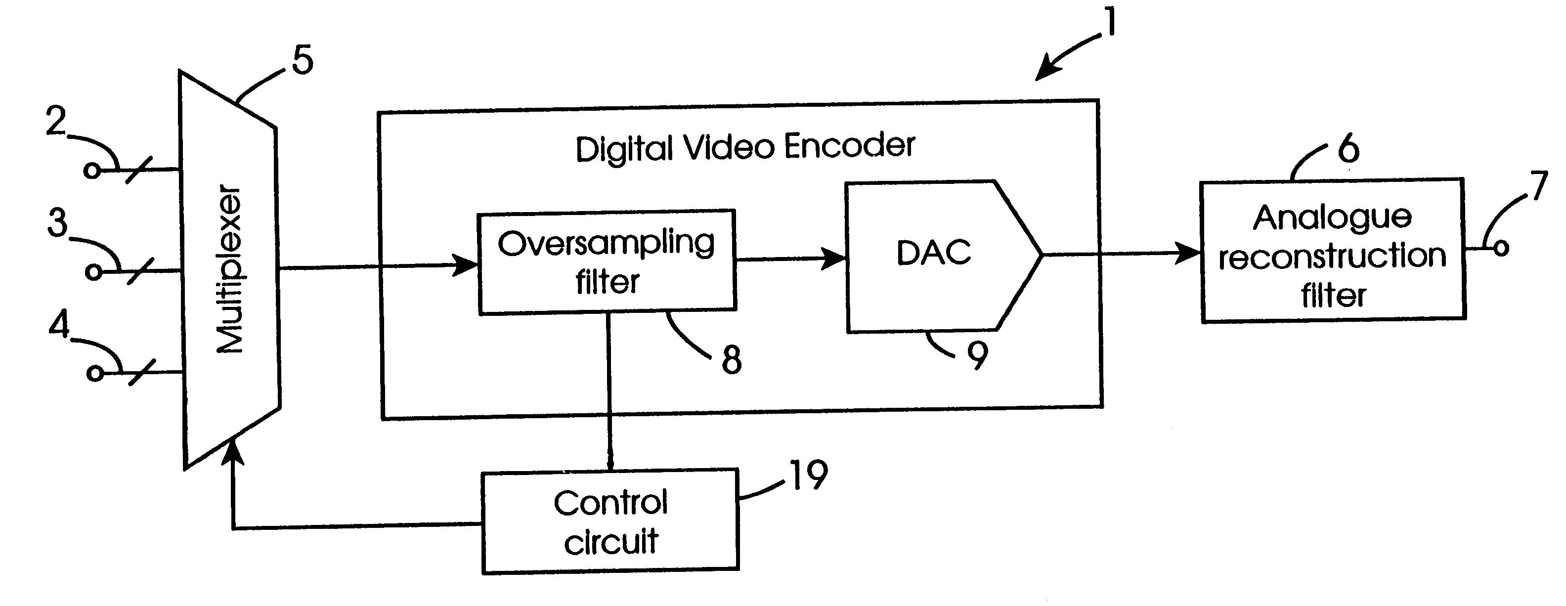
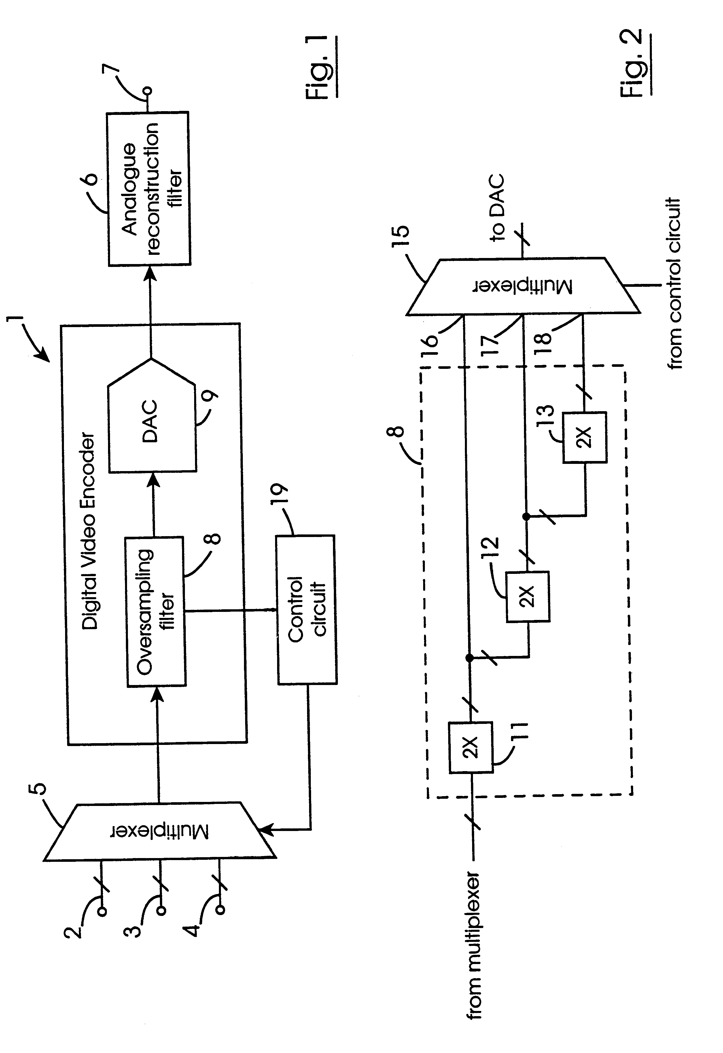
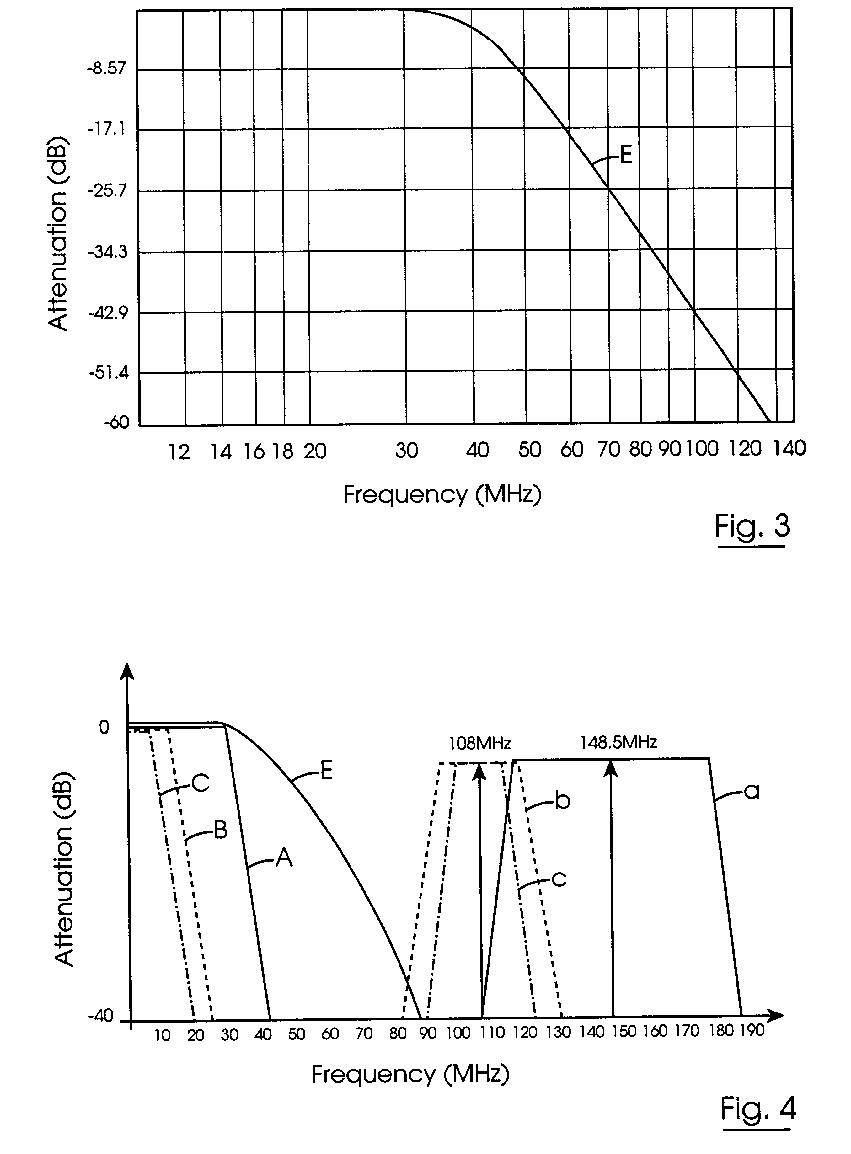
Referring to the drawings and initially to FIGS. 1 to 4 thereof, there is illustrated a block representation of a converter circuit indicated generally by the reference numeral 1, for carrying out a method according to the invention for converting a plurality of signals of different band widths from one of digital and analogue form to the other of the digital and analogue form. In this embodiment of the invention the converter circuit 1 is a digital to analogue converter circuit 1 for encoding and converting digital video data signals of three different formats, namely, standard definition format, progressive scan format and high definition format to analogue form. The standard definition format video data signals are applied on a first bus 2, and are of band width of 6 MHz. The progressive scan format video data signals are applied on a second bus 3, and are of band width of 12 MHz, while the high definition format video data signals are applied on a third bus 4, and are of band wi...


PUM


Abstract

A method for selectively and sequentially converting digital video data signals in three formats, namely, standard definition, progressive scan and high definition formats to analogue form such that the same analogue reconstruction filter can be used for filtering the analogue forms of the signals after conversion. The digital signals prior to being converted are over-sampled at respective over-sampling frequencies for displacing image frequencies to frequencies sufficiently spaced apart from the widest band width signal so that the analogue reconstruction filter can be provided for filtering the widest band width signal as well as the other band width signals and also can be provided with a relatively low roll-off rate of attenuation. The standard definition video data signals are over-sampled at eight times the nyquist sampling frequency, and the progressive scan signals are over-sampled at four times the nyquist sampling frequency, thus displacing image frequencies of the standard definition and progressive scan signals to 108 MHz, so that the centre frequency of the image frequency is displaced to 108 MHz. The high definition video signals are over-sampled at twice the nyquist sampling frequency, thus displacing the image frequency of the high definition signal to 148.5 MHz, so that its centre frequency is displaced to 148.5 MHz. This, thus, leaves a frequency band gap of approximately 66 MHz between the high definition band width signal and the closest image frequency, namely, that of the progressive scan signal. The method can also be applied to the conversion of analogue video signals to digital form whereby the same analogue anti-aliasing filter can be used for the analogue signals in the three formats.

Description

The present invention relates to a method for selectively and sequentially converting a plurality of signals from one of a digital and analogue form to the other of the digital and analogue form, wherein the signals are of different frequency band widths, so that the signals can be filtered in the same analogue filter in a common analogue path.BACKGROUND TO THE INVENTIONDigital video data signals are provided in three commonly used formats, namely, standard definition format, progressive scan format and high definition format. In standard definition format they may be provided in accordance with any of the following standards, PAL, NTSC and SECAM standards, in progressive scan format they may be provided in accordance with 525P and 625P standards, and in high definition they may be provided in accordance with 1080i, 720P and 1250i standards. In general, it is desirable that video signal processing units be capable of processing the video data signals in all three formats. Standard d...

Claims


Application Information

Patent Timeline
Patent Type & Authority Patents(United States)
IPC IPC(8): H04N7/01H04N5/14
CPCH04N5/14H04N7/0102H04N7/0125
Inventor BARRY, JOSEPH MICHAELCOTTER, MARTIN GERARD
Owner ANALOG DEVICES INC
Learn More