
Roulette wheel winning number detection system

a winning number and detection system technology, applied in the field of roulette wheel winning number detection system, can solve the problems of easy error in the method of identifying pockets in the roulette wheel, unpopular with casino managers, and difficult to align and inaccurately

Inactive Publication Date: 2003-09-09
TECHN CASINO SERVICES LTD
View PDF7 Cites 17 Cited by
  • Summary
  • Abstract
  • Description
  • Claims
  • Application Information

AI Technical Summary

Benefits of technology

Accordingly, one aspect of the present invention provides a detection system for detecting a winning number in a roulette wheel game in which video images of at least one pocket and at least one corresponding colored pocket number region in a one-fifth region of the roulette wheel are obtained. The system does not require an image of the whole roulette wheel. Thus the video camera used to obtain the video images can be mounted in a more convenient position, such as at the side of the roulette wheel.
To identify the pocket, processing is carried out on an array of points in an area corresponding to a pocket number region in the video image. The use of an array of points is robust and avoids errors due to reflections from the numbers provided in the pocket number regions and other spurious reflections. Once the pocket number region in the image has been identified, whether or not a ball is present in the corresponding pocket is determined by sampling a number of points in the image in a region of the pocket in which the ball would be expected to be present. If the ball is detected, the winning number is output as the identified corresponding pocket number region.
One aspect of the present invention provides for automatic identification of a first fixed area within the color pocket number region, and a corresponding second fixed area within a corresponding pocket in which the ball can be expected to lie. The automatic identification of the sampling areas can be achieved in view of the limited field of view over the roulette wheel, i.e., the image is of only a section of the roulette wheel. The identification is preferably further simplified by the use of a target which is placed in a predetermined pocket. The target is readily identifiable against the background of the roulette wheel. The location of the target can be carried out using any form of recognition technique, e.g., a correlation technique. Because the relationship between the pocket and the corresponding colored pocket number region is known, the search for the sampling area within the colored pocket number region is simplified once the position of the target has been determined, i.e., not all of the image need be searched to identify the area.
The present invention is, however, more preferably implemented using color video data from a color video camera. Using color video data, the identity of the pockets can be more easily determined by classifying the sample points in the first fixed area into four categories, i.e., red, black, green and white. The pixel categorization at the sample points can simply be determined by the use of thresholds. In one embodiment, the intensity is used to distinguish black and white, and a V component calculated in YUV color space is used to distinguish red and green. The present invention is not, however, limited to the use of intensity and V values, and any single color coordinates or multiple color coordinates in any color space can be used.

Problems solved by technology

This arrangement suffers from the disadvantages of being both difficult to align and inaccurate due to the use of analog electronics in the detection of reflected light.
This technique suffers from the disadvantage of requiring an image of the whole of the roulette wheel, thus requiring the video camera to be mounted above the roulette wheel such as in the ceiling of the casino.
Thus apart from the technical difficulties, this is unpopular with casino managers.
Only a line of points are taken through each pocket number region associated with the pocket, and thus this method of identifying pockets in the roulette wheel is prone to error.

Method used


Image

  • Roulette wheel winning number detection system
  • Roulette wheel winning number detection system
  • Roulette wheel winning number detection system

Examples


Embodiment Construction

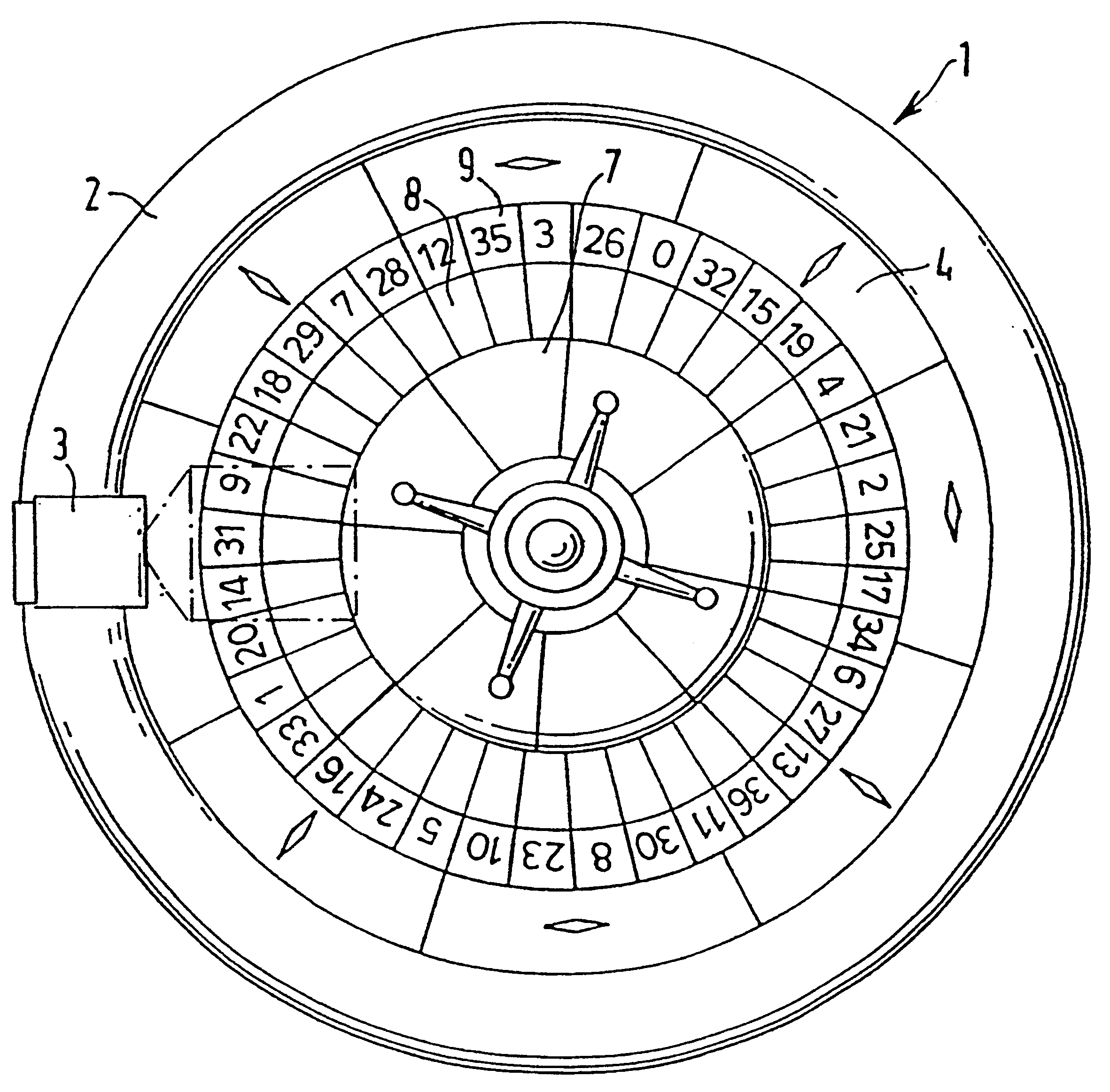
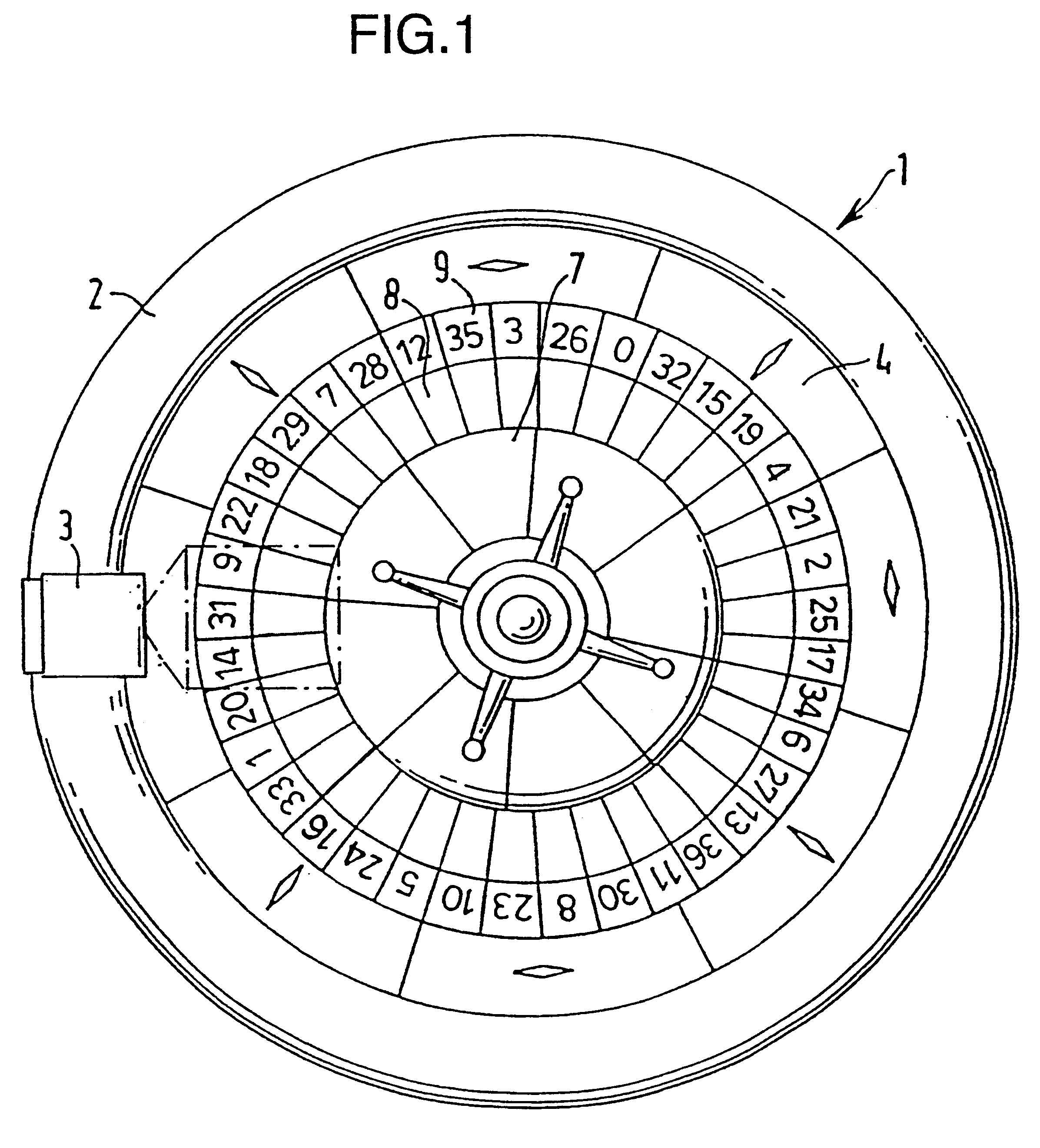
FIG. 1 is a plan view of a roulette wheel 1 having a rim 2 onto which is mounted a detector head 3, in accordance with an embodiment of the present invention for detecting the winning number during a roulette game.

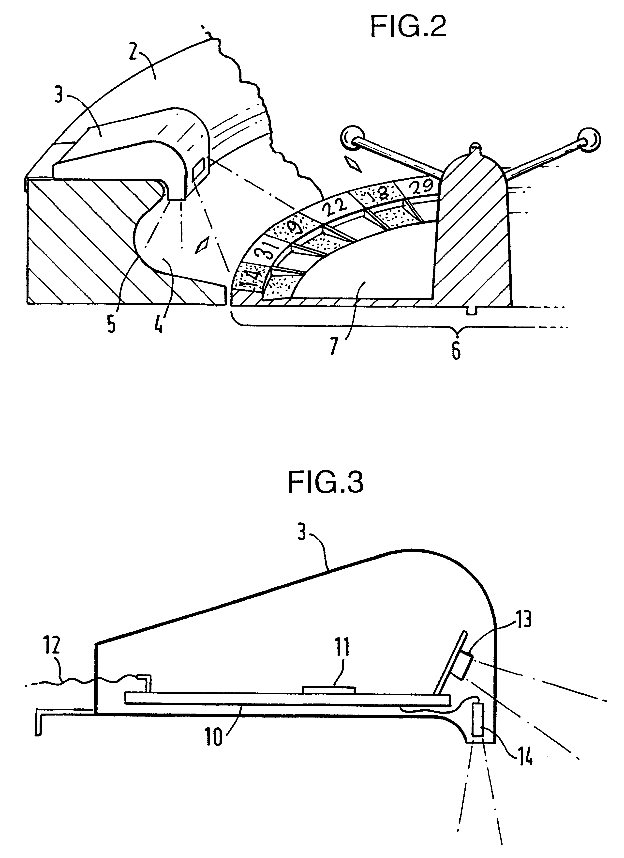
As shown in FIG. 2, the roulette wheel has a sloping surface 4 inside the rim 2 which joins the rim 2 at an undercut face 5 around which the ball is spun at the start of the roulette game. The detector head 3 is arranged to clamp over the rim 2 of the roulette wheel, and includes a sensor for detecting a ball passing in the undercut region 5 of the rim. In this way it can be detected that a ball is in play. The detector head 3 is also provided with a video camera to view a section of the roulette wheel including at least one pocket.

The central part of the roulette wheel comprises a cylinder 6 which is rotated during the game while the ball is spun around the undercut region 5 of the rim 2. On the cylinder 6 there is provided a sloping face 7. Referring again to FIG. 1, poc...


PUM


Abstract

Disclosed is a detection system for detecting a winning number in a roulette game played on a roulette wheel having pockets for receiving a ball and having colored pocket number regions corresponding to the respective pockets, including a video camera for generating a video image of the roulette wheel including at least one colored pocket number region and a corresponding pocket. The video data at an array of points in a first specified area of the color video image corresponding to a region through which the color pocket number region will pass are sampled when the cylinder of the roulette wheel is spun. The identity of the colored pocket number regions are determined from the sampled video data provided by the array of points. The video data is also sampled at a plurality of points in a second specified area in which the ball can be expected to be when in the pocket corresponding to the identified colored pocket number region. Whether or not the ball is in the pocket is determined using the sampled video data provided by the plurality of points and the identity of the identified colored pocket numbered region is output as the winning number if the ball is determined to be in the corresponding pocket.

Description

1. Technical Field of the InventionThe present invention generally relates to a system for detecting the winning number in a roulette game. Systems to detect the position of the ball in a roulette wheel are used both to illuminate a display to indicate the winning number to the players and to collect information for statistical processing. The latter enables the casino to detect that the wheel and its croupier are operating fairly and without bias.2. The Related ArtIn one prior art technique disclosed in WO 95 / 28996, a detection system is disclosed which uses modulated visible light and analog electronics in order to detect a ball in a pocket and to identify the pocket in which the ball lies. This arrangement suffers from the disadvantages of being both difficult to align and inaccurate due to the use of analog electronics in the detection of reflected light.In WO 95 / 11067, a security system is disclosed in which a video camera is used not only to monitor cheating at the gambling ta...

Claims


Application Information

Patent Timeline
Patent Type & Authority Patents(United States)
IPC IPC(8): A63F5/04G07F17/34G07F17/32A63F9/00
CPCA63F5/00G07F17/3213A63F2009/2435A63F2009/2445
Inventor PEARCE, HENRY COLINREAD, CHRISTOPHER LEWIS
Owner TECHN CASINO SERVICES LTD
Learn More