Eureka AIR delivers breakthrough ideas for toughest innovation challenges, trusted by R&D personnel around the world.

Vehicle lamp assembling apparatus

a technology for assembling apparatuses and lamps, which is applied in the manufacture of electrode systems, electric discharge tubes/lamps, optical radiation measurement, etc., can solve the problems of increasing the load on the control part and undesiredly increasing the lamp production cost, and achieve the effect of reducing the load on the equipment control par

Inactive Publication Date: 2003-08-26
KOITO MFG CO LTD
View PDF4 Cites 16 Cited by
  • Summary
  • Abstract
  • Description
  • Claims
  • Application Information

AI Technical Summary

Benefits of technology

In order to solve the problems in the above-described related art, the present invention provides a vehicle lamp assembling apparatus that reduces the load on the equipment control part of the apparatus main body by relocating some of the equipment controlling data--for working or inspection of the workpiece--to a non-contact-type memory card disposed on the jig.

Problems solved by technology

Therefore, the control data amount to be input to the control part increases with an increase in processing functions at the assembling apparatus, such as working and inspection, thereby increasing the load on the control part.
Therefore, high performance has been required for the control part, which high-performance requirement leads to undesirably increased lamp production costs.

Method used


Image

  • Vehicle lamp assembling apparatus
  • Vehicle lamp assembling apparatus
  • Vehicle lamp assembling apparatus

Examples


Embodiment Construction

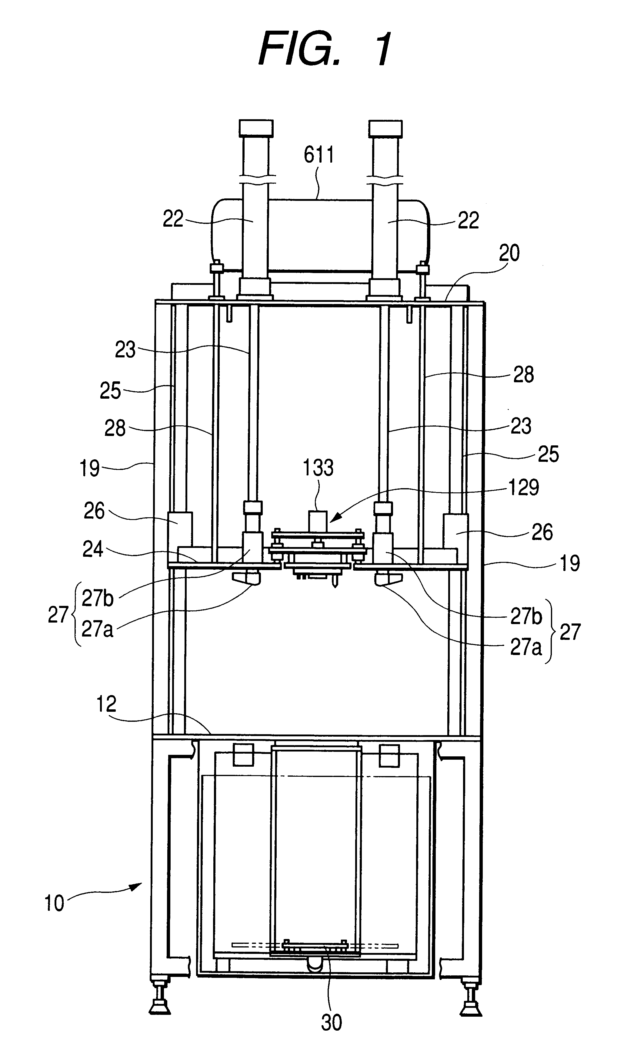
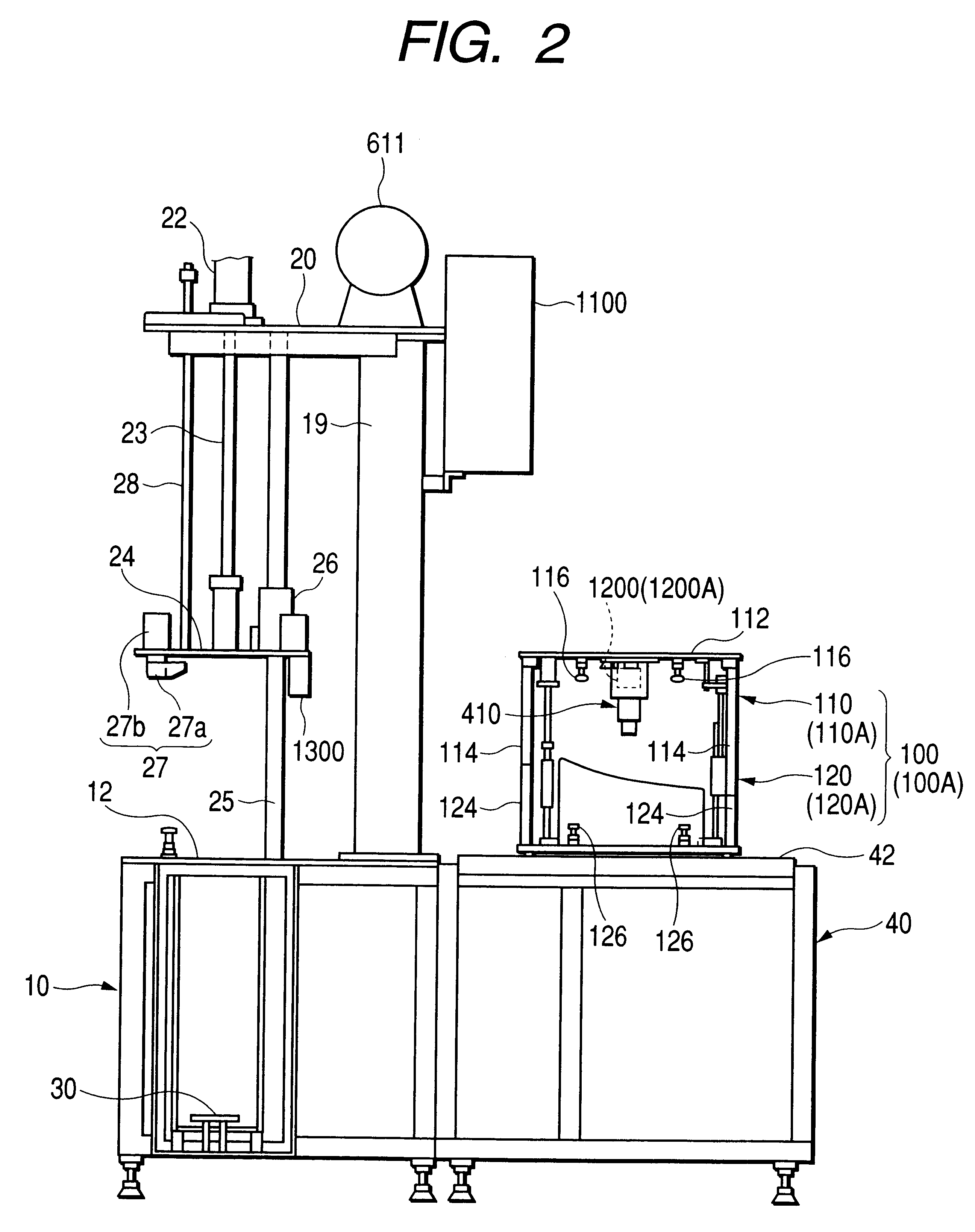
FIGS. 1 through FIG. 8 show a first embodiment of the present invention. In these drawings, the apparatus for inspecting the luminous intensity distribution of the headlamp is viewed from the front and the lateral side. The apparatus has an overall rectangular frame structure, and includes a base plate 12, a jig-supportive base 10, and a tip plate 20. A lower jig 120 can be mounted to the base plate 12 which, in turn, is disposed on the rectangular jig-supportive base 10. Further, the jig supportive base 10 is provided with a screen 30 on the inside thereof. The top plate 20 is supported by a pair of upright side frames 19 on the right and left, and is disposed above the jig supportive base 10. An upper jig supportive plate 24 is so disposed on the top plate 20 so as to be movable vertically with air cylinders 22 that are lift mechanisms.

During operation of the apparatus, a headlamp W is set on the jig supportive base 10 so as to be supported by the lower jig 120. Then, when a headl...


PUM

PropertyMeasurementUnit
Timeaaaaaaaaaa
Poweraaaaaaaaaa
Distributionaaaaaaaaaa

Abstract

An vehicle lamp assembling apparatus including a jig which supports a lamp component, an apparatus main body having disposed thereon positioning and fastening mechanisms (plungers and engagement holes) for positioning and fastening the jig to the apparatus main body. Some equipment (contact units) is disposed on the apparatus main body, and / or on the jig, for carrying out a predetermined processing, such as working or inspection, on the lamp component supported by the jig. Further, a control part is disposed on the apparatus main body, for drive control of the equipment. An ID plate that stores processing information, such as driving procedures and driving amount of the equipment, is disposed on the jig, whereas a non-contact memory reader is disposed on the apparatus main body so as to oppose the ID plate when the jig is fastened to the apparatus main body. The control part drives the equipment based on the processing information read from the ID plate via the memory reader. Thus, the amount of equipment-drive-control data stored in the control part of the apparatus main body is reduced, and the control part need not be a high-performance CPU.

Description

BACKGROUND OF THE INVENTION1. Field of the InventionThis invention relates to a lamp assembling apparatus that is installed in a vehicle lamp assembly line and, more specifically, relates to a lamp assembling apparatus in which a prescribed processing, such as working or inspection, is carried out. The prescribed processing is carried out on a work--such as a lamp or a lamp component--that is supported on the jig, through positioning and fastening the work with the jig, and through driving of the apparatus main body and / or of some equipment disposed on the jig.2. Description of the Related ArtA plurality of assembling apparatuses, where prescribed processing is carried out on the work, are installed in a head lamp assembly line. Each apparatus main body is provided with some equipment for carrying out the prescribed processing, and with a control part for controlling the equipment, wherein each control part is provided with preset control data for driving the equipment.A first appar...

Claims


Application Information

Patent Timeline
IPC IPC(8): G01M11/06F21S8/10H01J9/42B23P21/00H01J9/48
CPCG01M11/061H01J9/42H01J9/48Y10T29/53022Y10T29/53Y10T29/5303
Inventor ONUKI, FUJIOMATSUI, SHINOBU
Owner KOITO MFG CO LTD
Why Eureka
Eureka Blog
Learn More