
Method for constructing composite response surfaces by combining neural networks with other interpolation or estimation techniques

a composite response surface and neural network technology, applied in the field of improved methods and systems for design optimization using composite response surfaces, can solve the problems that the aerodynamic design optimization procedures that make efficient use of these advanced techniques are still in their infancy, and achieve accurate representation, reduce the amount of data required, and small amount of available training data.

Inactive Publication Date: 2003-08-12
NASA
View PDF3 Cites 36 Cited by
  • Summary
  • Abstract
  • Description
  • Claims
  • Application Information

AI Technical Summary

Benefits of technology

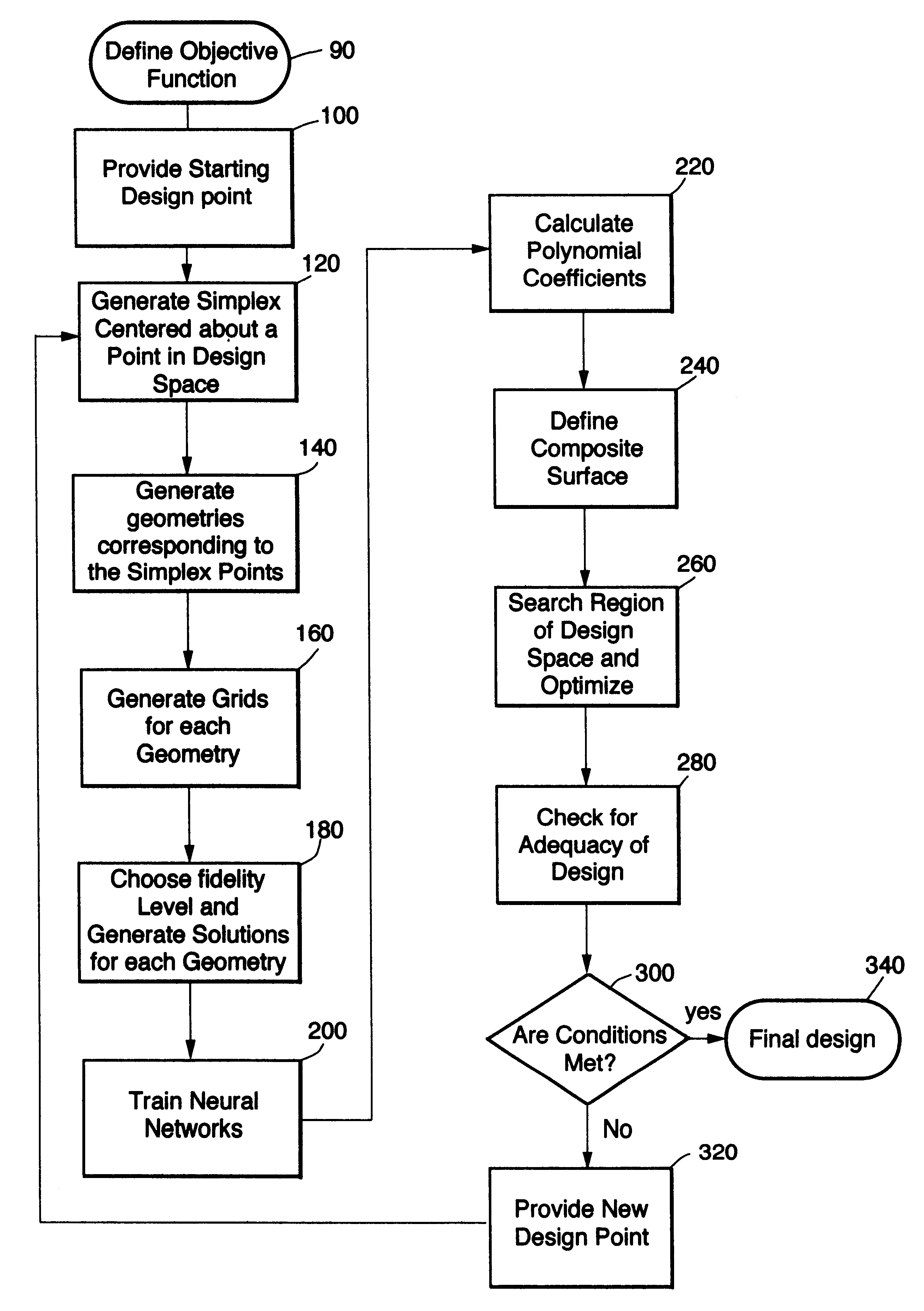
The present invention is directed toward an improved method and system for design optimization using composite response surfaces. These composite response surfaces are constructed by combining neural networks with other interpolation / estimation techniques such as polynomial fits. In particular, the present invention relates to a flexible process for the efficient use of simulation and experimental data in aerodynamic design optimization.
The present design method can be used to improve the unsteady aerodynamic performance of transonic turbines by optimizing the shape of the stator and rotor airfoils. This is accomplished by formulating an objective function that minimizes the unsteady amplitudes on the stator vane (or rotor blade) subject to the constraint that the tangential force on the rotor airfoil (i.e., turbine work output) does not decrease. The pressure amplitude is used as a measure of the unsteadiness in the flow field and is defined as the range of temporal pressure variation on the airfoil surface.

Problems solved by technology

However, aerodynamic design optimization procedures that make efficient use of these advanced techniques are still in their infancy.

Method used


Image

  • Method for constructing composite response surfaces by combining neural networks with other interpolation or estimation techniques
  • Method for constructing composite response surfaces by combining neural networks with other interpolation or estimation techniques
  • Method for constructing composite response surfaces by combining neural networks with other interpolation or estimation techniques

Examples


Embodiment Construction

OF PRACTICING THE INVENTION

The following applications have been chosen to demonstrate how some of the objectives of the invention have been met.

Metamorphosis of a Generic Shape Into an Optimal Airfoil

The present invention was used to reconstruct the shape of a turbine airfoil given the desired pressure distribution and some relevant flow and geometry parameters. The shape of the airfoil was not known a priori. Instead, it was evolved from a simple curved section of nearly uniform thickness. The evolved optimal airfoil closely matched the shape of the original airfoil that was used to obtain the pressure distribution. This constitutes a "blind" test. FIG. 5 illustrates the evolution of the design. The evolution of the shape of the airfoil is shown on the left, while the corresponding pressure distributions compared to the target pressure distribution are shown on the right. Clearly, the surface pressures approach the target pressure as the design progresses. The optimal airfoil shown...


PUM


Abstract

A method and system for design optimization that incorporates the advantages of both traditional response surface methodology (RSM) and neural networks is disclosed. The present invention employs a unique strategy called parameter-based partitioning of the given design space. In the design procedure, a sequence of composite response surfaces based on both neural networks and polynomial fits is used to traverse the design space to identify an optimal solution. The composite response surface has both the power of neural networks and the economy of low-order polynomials (in terms of the number of simulations needed and the network training requirements). The present invention handles design problems with many more parameters than would be possible using neural networks alone and permits a designer to rapidly perform a variety of trade-off studies before arriving at the final design.

Description

ORIGIN OF THE INVENTIONThe invention described herein was made by employees of the United States Government and may be manufactured and used by or for the Government for governmental purposes without the payment of any royalties thereon or therefor.1. Technical FieldThe present invention is directed toward an improved method and system for design optimization using composite response surfaces. These composite response surfaces are constructed by combining neural networks with other interpolation / estimation techniques such as polynomial fits. In particular, the present invention relates to a flexible process for the efficient use of simulation and experimental data in aerodynamic design optimization.2. Description of the Related ArtConsiderable advances have been made in the past two decades in developing advanced techniques for the numerical simulation of fluid flows over aerodynamic configurations. These techniques have now reached a level of maturity where they can be used routine...

Claims


Application Information

Patent Timeline
Patent Type & Authority Patents(United States)
IPC IPC(8): G06F17/50
CPCG06F17/5095G06F2217/44G06F30/15G06F2113/26
Inventor RAI, MAN MOHANMADAVAN, NATERI K.
Owner NASA
Learn More