
Modified first-order digital PLL with frequency locking capability

a technology of frequency locking and digital pll, applied in the field of first-order digital pll, can solve the problems of analog pll's present, relatively difficult to effectively migrate to a new process technology, and analog pll's are typically sensitive to nois

Inactive Publication Date: 2003-08-12
AVAGO TECH WIRELESS IP SINGAPORE PTE
View PDF5 Cites 28 Cited by
  • Summary
  • Abstract
  • Description
  • Claims
  • Application Information

AI Technical Summary

Benefits of technology

Preferably, both the FLL and the frequency synthesizer include a phase/frequency detector, a charge pump connected to the phase/frequency detector, a loop filter connected to the charge pump, a voltage-to-current converter connected to the loop filter, and a current-controlled oscillator connected to the voltage-to-current converter. Preferably, the FLL is configured to disconnect the loop filter from the charge pump when no incoming data stream is received by the FLL. Preferably, the FLL is configured to connect the loop filter to the charge pump when the FLL receives the incoming data stream. Preferably, the current-controlled oscillat

Problems solved by technology

Unfortunately, analog PLL's present several disadvantages.
Additionally, the structure and characteristics of analog PLL's typically often render it relatively difficult to effectively migrate to a new process technology.
Still further, analog PLL's are typically sensitive to noise.
Because analog PLL's present certain disadvantages, some of which have been discussed above, it is sometimes advantageous to utilize a digital PLL instead of utilizing an analog PLL in disk drives.
As a result, the loop bandwidth will be too wide to reject any transient noise.
Unfortunately, it is difficult to design a second-order digital PLL that can meet all the requirements of a disk drive application.
Furthermore, a second-order digital PLL is typically much more complex than a first-order digital PLL, and typically consumes more power and chip area.

Method used


Image

  • Modified first-order digital PLL with frequency locking capability
  • Modified first-order digital PLL with frequency locking capability
  • Modified first-order digital PLL with frequency locking capability

Examples


Embodiment Construction

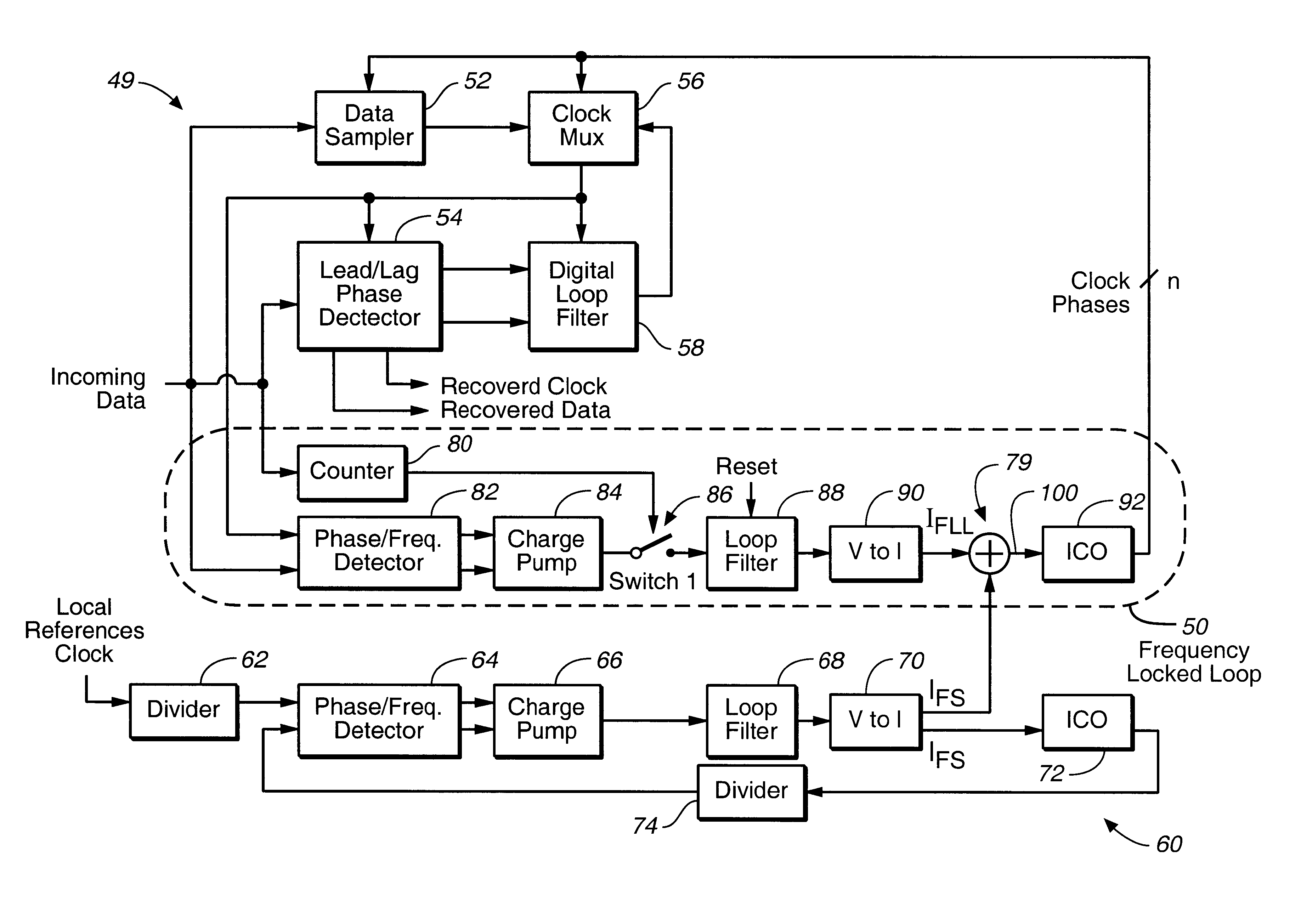
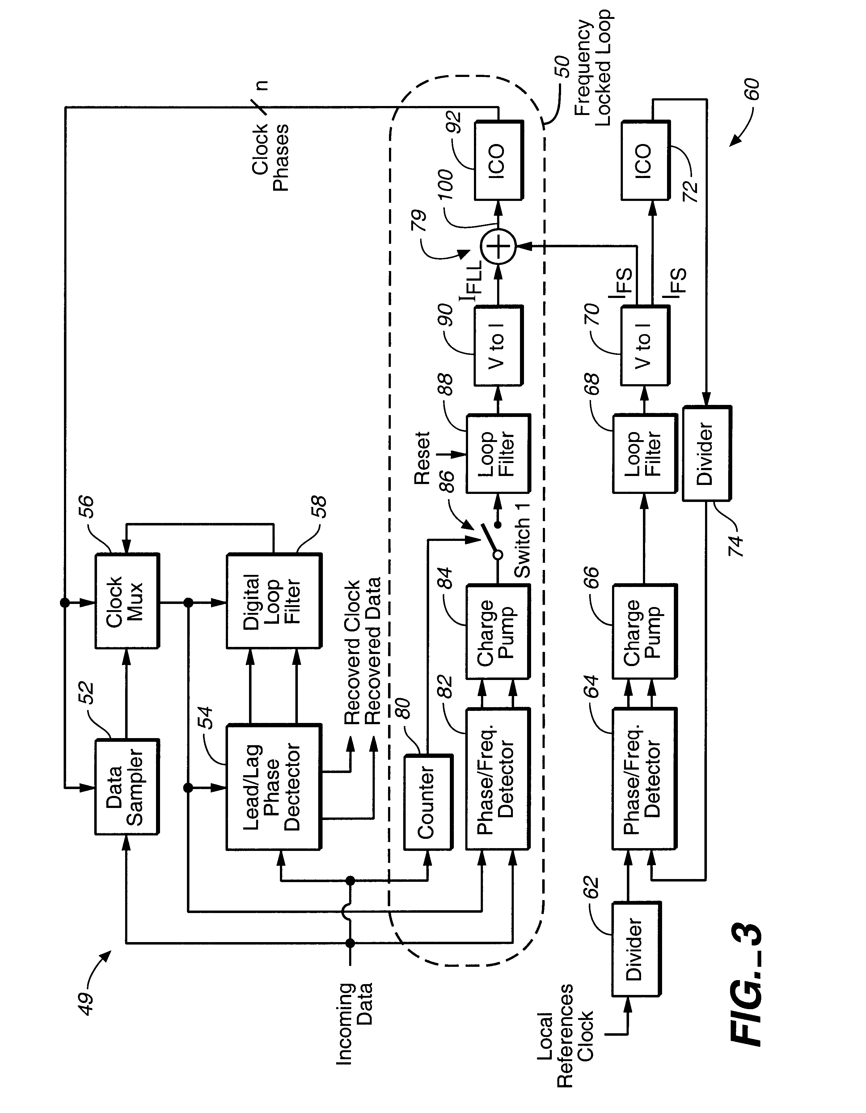
FIG. 3 illustrates a first-order digital PLL 49 which is in accordance with an embodiment of the present invention. The PLL 49 illustrated in FIG. 3 includes many of the same components as does the PLL 18 illustrated in FIG. 2, but also includes a frequency-locked loop (FLL) 50. As will be described more fully herein, the FLL 50 effectively tracks out the frequency difference between a clock signal embedded in the incoming data and local reference clock and provides that the PLL 49 can accommodate large frequency differences.

The PLL 49 shown in FIG. 3, like the PLL 18 shown in FIG. 2, includes a data sampler 52 and a lead / lag phase detector 54 (identified in FIG. 3 as "Lead / Lag PD"), both of which receive incoming data having a clock signal embedded therein. The PLL 49 also includes a clock multiplexer 56 (identified in FIG. 3 as "Clock MUX") and a digital loop filter 58 (identified in FIG. 3 as "Digital LF"). The PLL 49 also includes a frequency synthesizer 60 which, like the frequ...


PUM


Abstract

A first-order digital PLL configured to accommodate a large frequency difference between a clock signal embedded in an incoming data stream received by a phase-locked loop and a local reference clock signal received by a phase-locked loop circuit. The PLL includes a data sampler which receives the incoming data stream, a frequency-locked loop (FLL) which receives the incoming data stream and is connected to the data sampler, and a frequency synthesizer which receives the local reference clock signal and is connected to the FLL. The FLL is provides a signal having a frequency which is substantially equal to the frequency of the local reference clock signal when no incoming data stream is received by the FLL, and provides a signal having a frequency which is substantially equal to the frequency of the incoming data stream when the FLL receives the incoming data stream.

Description

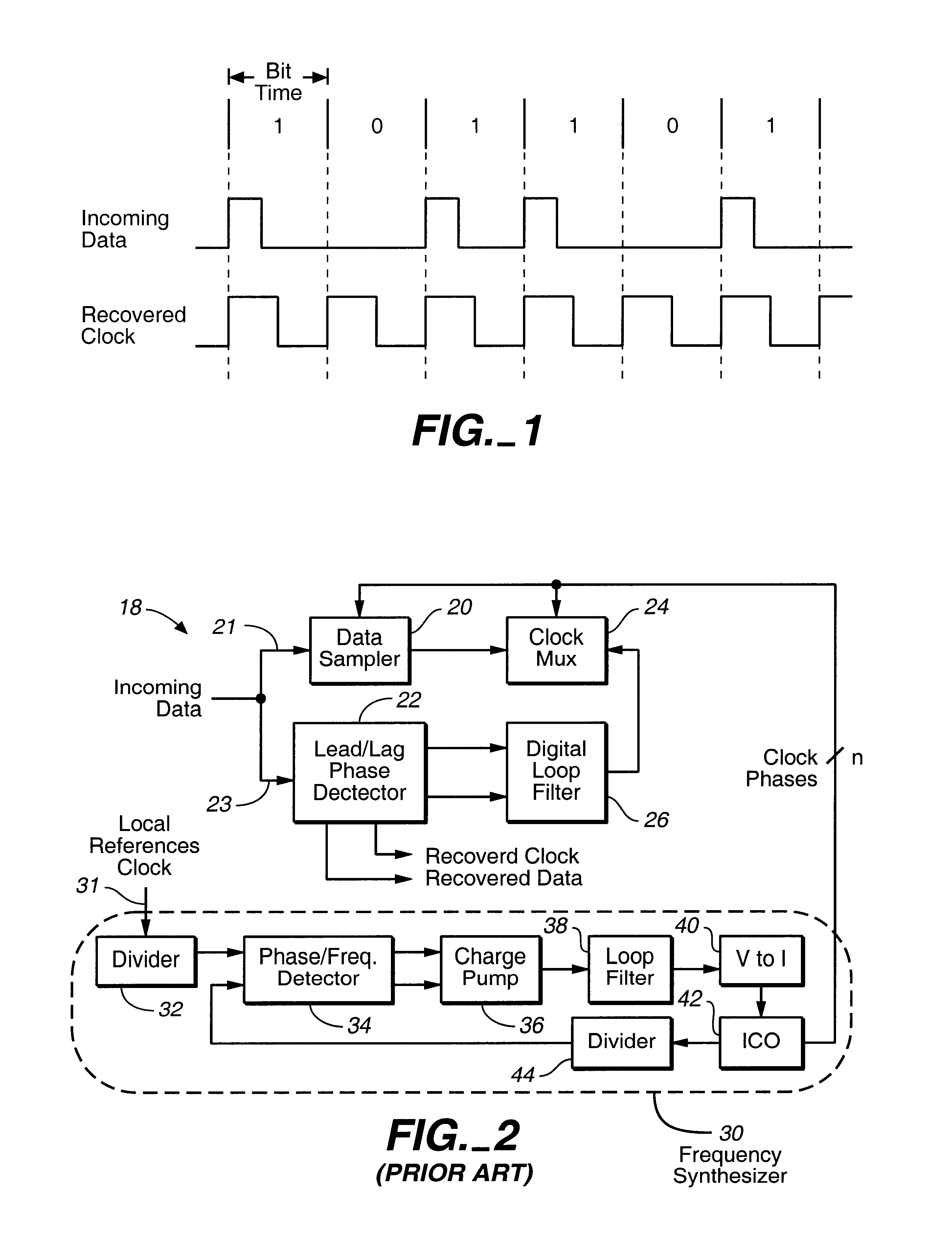
The present invention relates generally to phase-locked loops, and more specifically relates to a modified first-order digital phase-locked loop which is configured to accommodate large frequency differences.Typically, when data is read from a disk drive, a read channel chip inside the disk drive extracts an embedded clock signal from a data stream. The embedded clock signal which is extracted from the data stream is often referred to as the "recovered clock." FIG. 1 illustrates typical waveforms of incoming data and a "recovered clock" in a disk drive read application.Usually, an analog phase-locked loop (PLL) is used to extract the clock signal from the incoming data. Unfortunately, analog PLL's present several disadvantages. For example, the performance of an analog PLL is typically quite sensitive to process, temperature and supply voltage variations. Additionally, the structure and characteristics of analog PLL's typically often render it relatively difficult to effectively mig...

Claims


Application Information

Patent Timeline
IPC IPC(8): H03L7/087H03L7/08H03L7/081H03L7/07H03L7/16H03L7/18H04L7/04H04L7/033
CPCH03L7/07H03L7/0805H03L7/081H03L7/087H03L7/18H04L7/0332H04L7/0337H04L7/046
Inventor CHEN, DAO-LONG
Owner AVAGO TECH WIRELESS IP SINGAPORE PTE
Learn More