
Propelling and driving system for boats

a propulsion system and boat technology, applied in marine propulsion, special-purpose vessels, vessel construction, etc., can solve the problems of increasing the number of boats, increasing the complexity of logistic systems, and reducing the number of ships

Inactive Publication Date: 2003-07-15
SIEMENS AG
View PDF7 Cites 96 Cited by
  • Summary
  • Abstract
  • Description
  • Claims
  • Application Information

AI Technical Summary

Benefits of technology

A drive and propulsion system designed in such a way takes account, to a major extent, of the increasingly more stringent requirements for the reliability and safety of a ship. This is primarily due to the presence of at least two identical steering propellers with an autonomous control and regulation device, which results in homogeneous redundancy in the propulsion system. When a fault event occurs in a mechanical or electrical component of a steering propeller, there is thus at least one spare drive available, which ensures the maneuverability of the ship.
The invention is furthermore based on the object of developing the initially mentioned drive and propulsion system such that the electric propeller motor can be accelerated, decelerated or electrically braked without any risk of problems, caused by fast load changes, in the on-board power supply network or in the area of the diesel generator system.

Problems solved by technology

One disadvantage in this case is the considerable logistic complexity and hence considerable cost, which is further increased by the fact that both the manufacture of the individual components and the wiring and testing of the complete system necessitates inspection by a Classification Organization for example the American Bureau of Shipping (ABS), Bureau Veritas (BV), Der Norske Veritas (DNV), Germanischer Lloyd (GL) or Lloyds Register of Shipping (LRS).
This is primarily due to the presence of at least two identical steering propellers with an autonomous control and regulation device, which results in homogeneous redundancy in the propulsion system.
Ship propulsion systems, in particular steering propeller propulsion systems, produce oscillations during operation which propagate through the entire ship's hull and cause vibration in it.
However, this is not the case since, in particular, even a ship's propeller represents an oscillating load for the propulsion system, to be precise because the propeller blades partly move along the skeg or propeller-shaft stay (which is fitted to the ship's hull) during their rotational movement but, in contrast, can move largely free from this stay during another part of their rotational movement.
This method is on the one hand expensive while, on the other hand, it reduces the maximum permissible cargo weight in the ship, increases the fuel consumption and, furthermore, although it may reduce the material-destructive effects of the oscillations produced by the propulsion system, cannot, however, eliminate the cause.
Any fluctuation in the angle of advance of the propeller reduces the cavitation safety margin of a propeller since, in this case, the operating point of a propeller approaches or exceeds its cavitation limit.
Particularly in the region of a skeg or propeller-shaft stay fitted to the ship's hull, the operating point of the propeller can reach or exceed the cavitation limit, thus initiating cavitation which can then cause considerable damage to the ship and, in particular, to the propeller.
Cavitation also leads to unacceptable pressure fluctuations and noise which, in particular, considerably reduces the operational value of passenger, research and military ships.
One side effect in this case is that the rotation speed of the propeller does not remain exactly constant, but is subject to certain fluctuations, caused by the changing load.
However, this is of very minor importance for the forward propulsion produced by the propeller.
A further exasperating factor is that the values quoted there are often no longer satisfied these days, owing to lack of adequate maintenance, particularly in the upper power region.
This time gradient must not be exceeded, even in places, since otherwise, the diesel engine may be damaged.
If the propulsion system for ship's propellers exceed the dynamic limits of the diesel engines in the diesel generator system, the frequency of the on-board power supply network supplied by the diesel generator system fluctuates to unacceptable extents.
It is also possible for the diesel engines to be damaged, since the rotation speed control for the diesel generator system must keep the frequency of the on-board power supply network within a permissible range irrespective of the dynamic limits.
If the dynamic limits of the synchronous generators in the diesel generator system are exceeded, the voltage of the on-board power supply network fluctuates unacceptably.
In this case, it was often only possible to optimize specific operating points.
Otherwise, considerable beat frequencies would occur in the electric propeller motor, and these would appear as mechanical oscillations or structure-borne sound sources in the ship, in particular, there would be a risk of the ship's propeller starting to cavitate, which in turn could lead to damage to the ship's propeller and to the ship.
This thus leads to voltage fluctuations in the on-board power supply network, since the excitation for the synchronous generators in the diesel generator system can no longer follow the rate of change of the current nominal value.
This has the unpleasant effect for ship control that the drive and propulsion system drops into a hole when accelerating over certain rotation speed ranges, and effectively stops.
Furthermore, the power demand pumped by the drive and propulsion system from the ship's on-board power supply network is therefore also undesirable, since it necessitates an unnecessary power margin in the on-board power supply network.
The ramp transmitters used in the past for drive devices for ship's propellers which were controlled in steps are unable to assign a defined acceleration torque to the electric propeller motor during acceleration processes and, in fact, they simply produce only the respective current limits appropriate at that time over wide rotation speed ranges of the electric propeller motor.

Method used


Image

  • Propelling and driving system for boats
  • Propelling and driving system for boats
  • Propelling and driving system for boats

Examples


Embodiment Construction

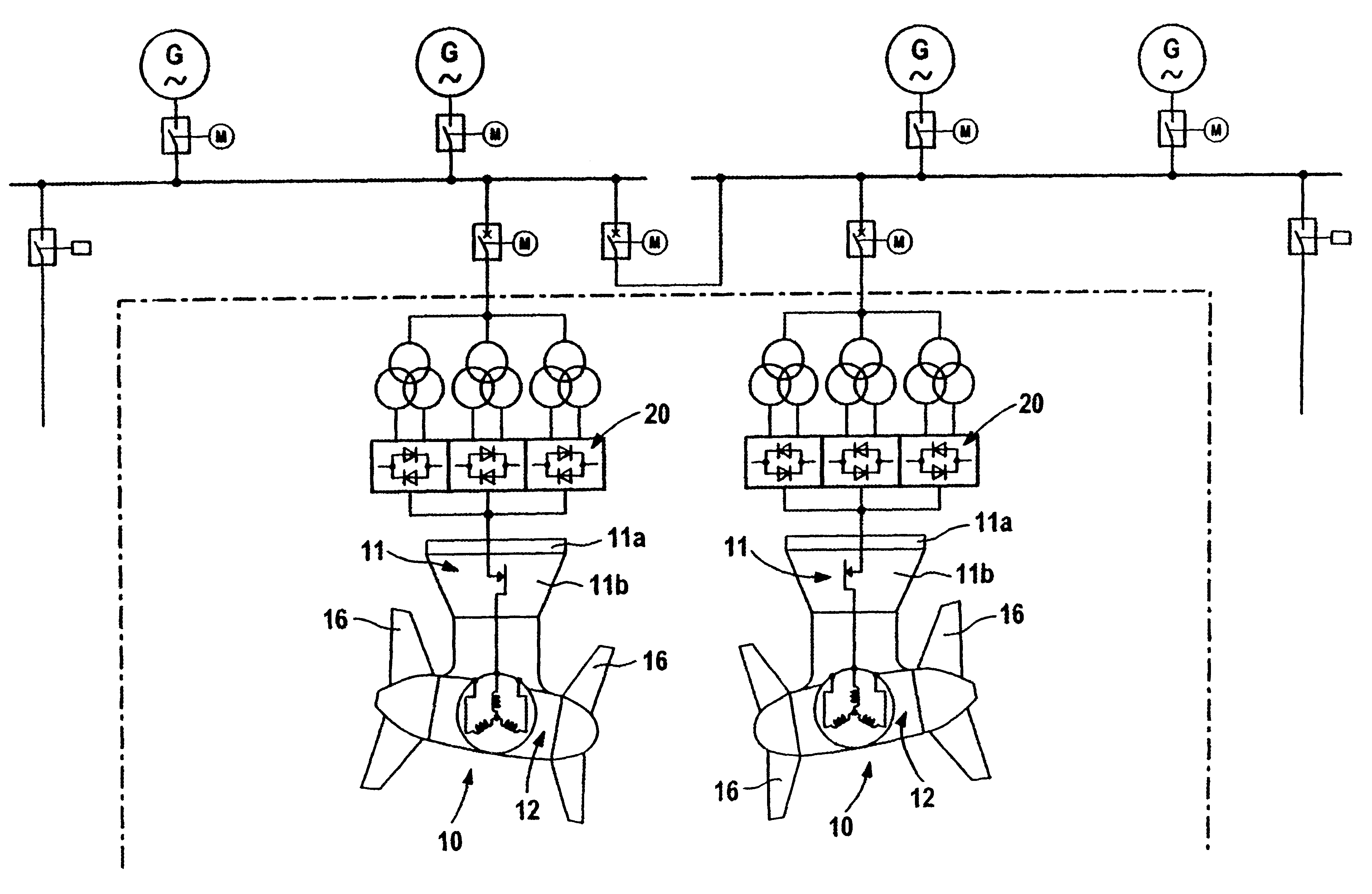
Exemplary embodiment drive and propulsion systems are shown in FIGS. 1 and 2. Each embodiment has a steering propeller 10, comprising an azimuth module 11 and a propulsion module 12, which is fitted to it like a pod. The azimuth module 11 can be connected via a fixed part 11a to the hull of a ship. An azimuth drive 13 is arranged in the fixed part 11a of the azimuth module 11, is controlled by an azimuth controller 70, which is located in the ship, and drives a part 11b of the azimuth module 11 which can rotate.

Furthermore, a power transmission device 14 is arranged in the fixed part 11a of the azimuth module 11 and connects a drive motor, located in the propulsion module 12, to the ship's on-board power supply network. The part 11b of the azimuth module 11 which can rotate has auxiliary functions, for example for electrical supply or control. The drive motor arranged in the propulsion module 12 is in the form of a permanent magnet synchronous machine and drives two propellers 16.

Th...


PUM


Abstract

A propelling and driving system for boats having an outboard rudder propeller. The system provides the boat with reliable and comparatively good maneuverability. The system comprises at least two rudder propellers, each having driving motors configured in the form of a permanent magnet-excited synchronous machine. The stator winding of each synchronous machine has three winding phases connected to a three-phase alternating current, which are connected to the supply system of the boat. A modular controlling and regulating device comprising standardized modules is provided for each of the rudder propellers.

Description

1. Field of the InventionThe present invention relates to drive and propulsion systems for ships. In particular, drive and propulsion system having a steering propeller arranged outboard, comprising an azimuth module which can rotate and has a power transmission device, and a propulsion module arranged like a pod on the azimuth module and provided with a drive motor for a propeller.2. Discussion of the Related ArtA drive technology such as this, which is also known in practice by the expression SSP, is a ship propulsion system which can be rotated, is preferably arranged in the region of the stern of a ship, and at the same time carries out the functions of propulsion, steering and lateral thrust production. The SSP drive is furthermore distinguished by producing little drag on the ship even with the most widely differing ship hull designs, and requires no additional cooling, since this is provided by the water flowing around the drive motor in the propulsion module. Furthermore, th...

Claims


Application Information

Patent Timeline
IPC IPC(8): B63H5/16B63H1/12B63H23/24B63H5/08B63H5/125B63H21/22B63H23/00B63H21/00B63H5/00B63H1/00B63B1/00B63B1/04B63H5/10B63H25/42B63J99/00
CPCB63B1/042B63H1/12B63H5/08B63H5/125B63H5/16B63H21/22B63H23/24B63H5/10B63H2005/1258B63H25/50
Inventor GEIL, GUNTERHOES, STEFANRZADKI, WOLFGANG
Owner SIEMENS AG
Learn More