
Banknote handling machine

a technology of handling machine and banknote, applied in the field of banknote handling machine, can solve the problems of greater limitations of the latter

Inactive Publication Date: 2003-06-24
NYBOHOV DEVELOPMENT AB
View PDF13 Cites 30 Cited by
  • Summary
  • Abstract
  • Description
  • Claims
  • Application Information

AI Technical Summary

Benefits of technology

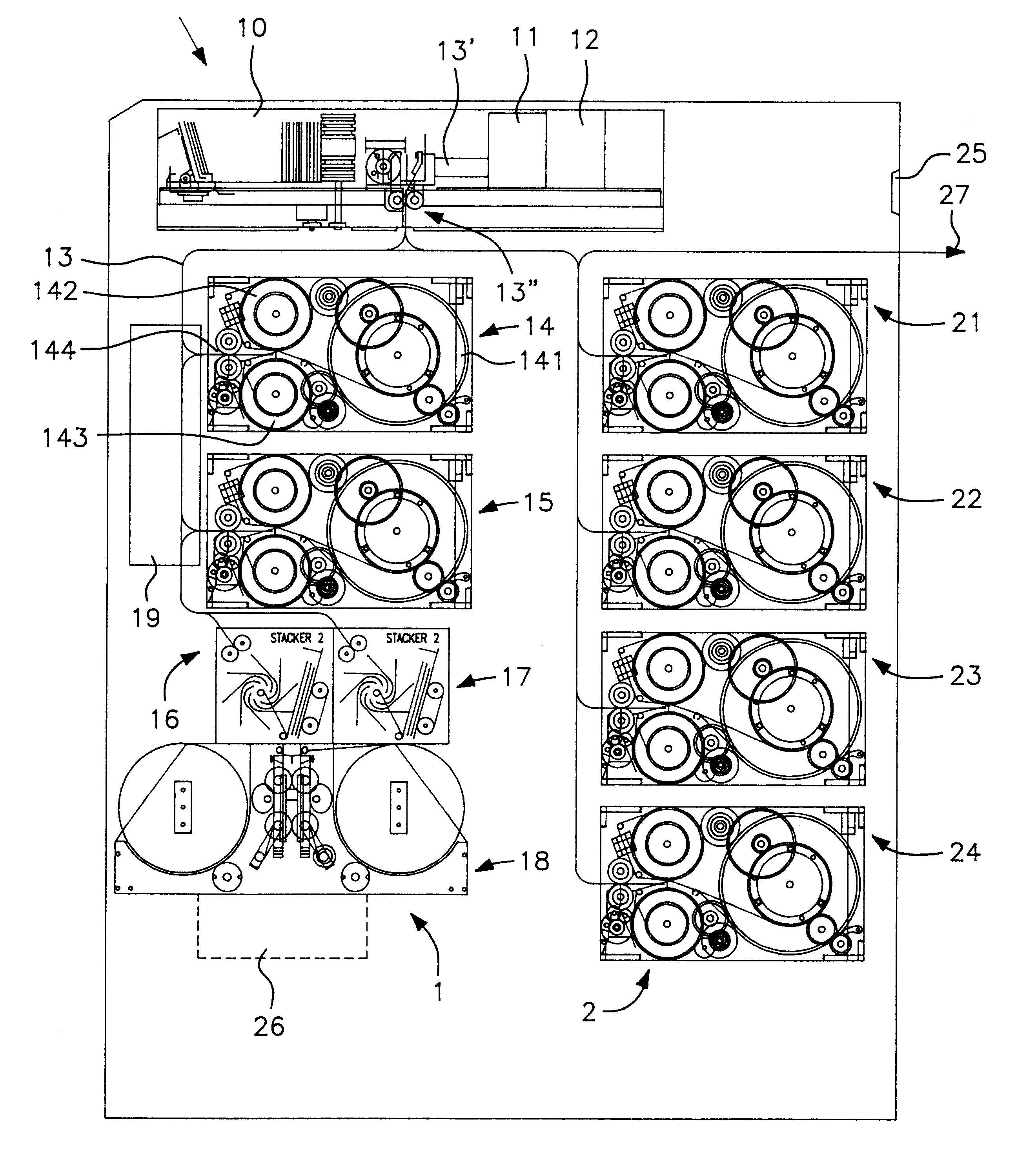
Generally speaking, the major part of the banknotes fed into the infeed part 1 and then accepted will be transported directly to the outfeed part 2, whereas surplus accepted banknotes will be stored in the infeed part 1 for later packaging in the packaging unit 18 in disposable cassettes if desired, these cassettes being collected in a space 26 beneath the packaging unit. The disposable cassettes will preferably accommodate one-hundred bundles of banknotes together with a receipt, the text of which is printed conveniently on the inner surface of the package or cassette immediately before commencing the packaging operation. This organisation of the mechanical function of the machine will greatly increase the capacity of the machine and result in much greater flexibility and more economic handling of banknotes than earlier known banknote handling apparatus.
Sorting of banknotes with respect to quality and with respect to banknotes that must be destroyed, simplifies machine handling and facilitates the work associated with the destruction of banknotes outside the machine (carried out under the management of the National Central Bank).

Problems solved by technology

These and similar automatic apparatus have been found to function reasonably well in practice, although they have their limitations with respect to greater freedom in the flow of banknotes, i.e. as opposed to shutting off excessively large volumes of banknotes in one and the same place (costs interest), the ability to replenish an automatic cash dispenser or automatic telling machine with banknotes during the daytime without opening the security box, and enhanced security with respect to the transportation of any surplus banknotes from one place to another place where a banknote deficiency exists.

Method used


Image

  • Banknote handling machine
  • Banknote handling machine

Examples


Embodiment Construction

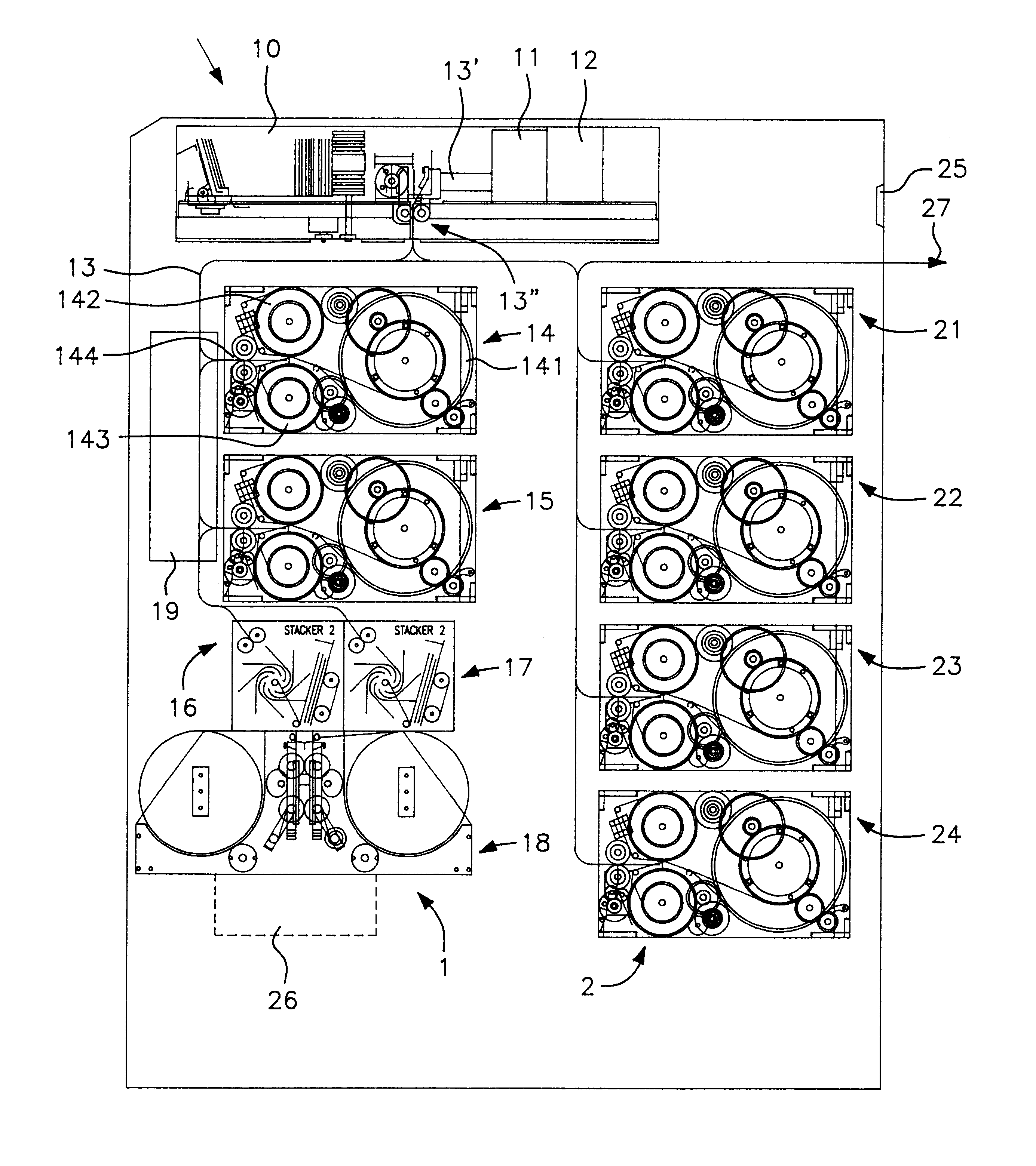
The invention will now be described in more detail with reference to the accompanying drawing which illustrates schematically a banknote handling machine constructed in accordance with the invention.

Further scope of applicability of the present invention will become apparent from the detailed description given hereinafter. However, it should be understood that the detailed description and specific examples, while indicating preferred embodiments of the invention, are given by way of illustration only, since various changes and modifications within the spirit and scope of the invention will become apparent to those skilled in the art from this detailed description.

The inventive banknote handling machine includes a banknote infeed part 1 and a banknote outfeed part 2.

The infeed part 1 includes a banknote depositing compartment 10, detector means 11, processing unit 12, transport path 13'-13"-13, first storage means 14, second storage means 15, first stacking means 16, second stacking ...


PUM


Abstract

A banknote handling machine having an infeed part for receiving externally posted banknotes and including a detector mechanism for checking the genuineness, quality and value of posted banknotes. The detector mechanism functions to sort false banknotes and banknotes of poor quality from remaining banknotes. A processor unit controls transportation of poor quality banknotes along a transport part to a unit for storing and packaging the banknotes, and the transportation of at least part of the remaining, genuine and accepted banknotes to a first storage unit for storing and packaging these banknotes in accordance with their denomination. An outfeed part enables banknotes ordered externally via a banknote ordering means to be dispensed from a second storage device. The processor unit controls the transportation of genuine and accepted banknotes primarily to the second storage device in the outfeed part and only secondarily to a first storage device in the infeed part.

Description

The present invention relates to a banknote handling machine, and more specifically to a machine that includes an infeed part for receiving banknotes that are posted from outside the machine and including detector means for checking the whether the banknotes are genuine or not, and the quality and denomination of said banknotes.In a further development of the invention, the banknote handling machine also includes an outfeed part for dispensing banknotes from a banknote storage means in response to an order given through the medium of an externally located banknote ordering means.BACKGROUND PRIOR ARTDual-purpose automatic apparatus for dispensing and depositing banknotes are known to the art; c.f. U.S. Pat. No. 4,447,714 in this respect. It is also known to provide detection means for checking deposited banknotes; c.f. European Patent Specification 0.213.094 in this respect. These and similar automatic apparatus have been found to function reasonably well in practice, although they h...

Claims


Application Information

Patent Timeline
IPC IPC(8): G07D11/00G07D13/00B07C1/00
CPCB65H29/006G07D11/0081G07D11/0006B65H2301/4191B65H2701/1912B65H2301/41912G07D11/12G07D11/40
Inventor LUNDBLAD, LEIF
Owner NYBOHOV DEVELOPMENT AB
Learn More