
Method for driving the TFT-LCD using multi-phase charge sharing

a technology of thin film transistor and charge sharing, applied in the direction of static indicating devices, non-linear optics, instruments, etc., can solve the problems of deterioration of liquid crystal and tft property, higher image quality requires higher power consumption, and the effect of increasing the power consumption of conventional tft-lcd

Inactive Publication Date: 2003-06-03
SAMSUNG DISPLAY CO LTD
View PDF6 Cites 34 Cited by
  • Summary
  • Abstract
  • Description
  • Claims
  • Application Information

AI Technical Summary

Benefits of technology

This approach reduces power consumption by two-thirds, decreases heat generation, and addresses reliability issues by eliminating the need for additional source drivers, thereby enhancing the stability and performance of high-resolution TFT-LCDs.

Problems solved by technology

When the positive and negative video signals are alternately provided to the liquid crystal on the basis of VCOM, however, light transmission curves of the liquid crystal do not accord with each other, resulting in flicker.
A higher image quality requires higher power consumption because the number of the generation of polarity conversions increases in proportional to the image quality.
Furthermore, the conventional TFT-LCD consumes a larger quantity of power to increase the generation of heat in case where its TFT is configured of a polysilicon TFT.
Accordingly, the characteristic of the liquid crystal and the property of the TFT are deteriorated due to the heat generated.
This narrows the line pitch, bring about reliability problems.

Method used


Image

  • Method for driving the TFT-LCD using multi-phase charge sharing
  • Method for driving the TFT-LCD using multi-phase charge sharing
  • Method for driving the TFT-LCD using multi-phase charge sharing

Examples


Embodiment Construction

Reference will now be made in detail to the preferred embodiments of the present invention, examples of which are illustrated in the accompanying drawings.

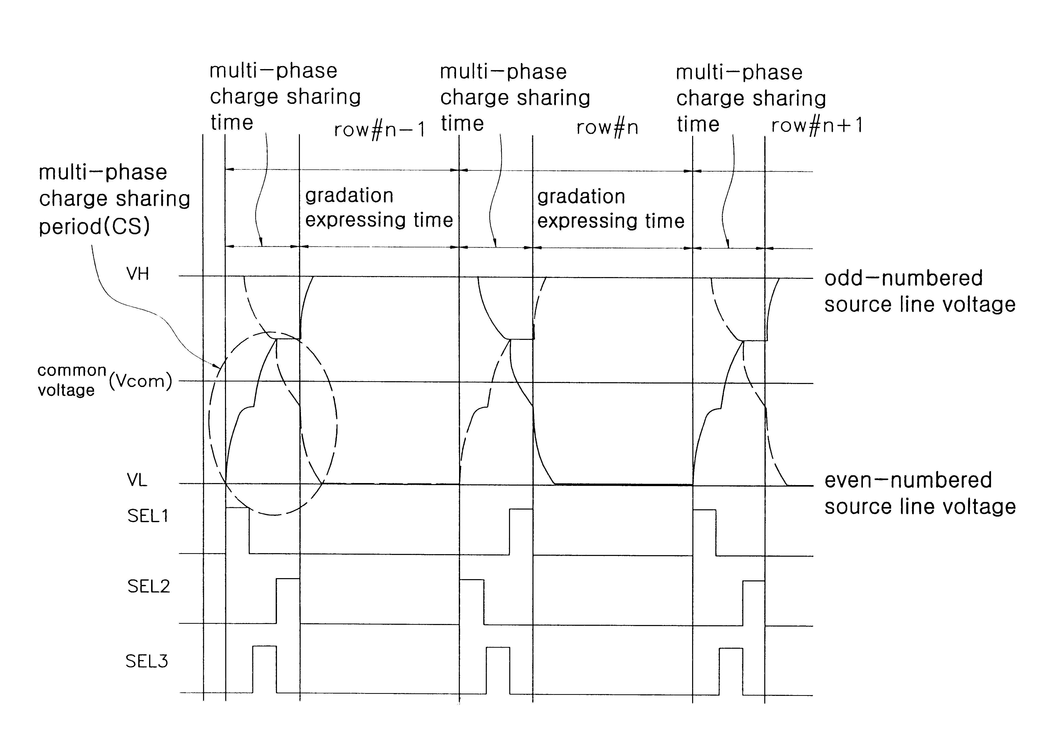
There will be described below a TFT-LCD using multi-phase charge sharing according to a preferred embodiment of the present invention with reference to the attached drawings. Referring to FIG. 5, the TFT-LCD using multi-phase charge sharing according to the present invention includes a line driver 200 which outputs video data signals each of which corresponds to each pixel through a plurality of source lines, a liquid crystal panel 100 for displaying the video signals applied through the source lines, and an external capacitor 500, connected between the line driver 200 and the liquid crystal panel 100, for collecting charges of source lines having a voltage higher than a common electrode voltage and supplying them to source lines having a voltage lower than the common electrode voltage when the source lines are connected thereto.

T...


PUM

PropertyMeasurementUnit
voltageaaaaaaaaaa
polarityaaaaaaaaaa
voltageaaaaaaaaaa

Abstract

There is provided a method for driving the TFT-LCD using multi-phase charge sharing, in which odd-numbered source lines and even-numbered source lines are connected to an external capacitor through a switching element during a period of multi-phase charge sharing time, to share the charges charged in the source lines. The method includes: a first charge sharing step in which even-numbered capacitors, which have been discharged with a voltage VL during a period of (N-1)th gradation expressing time, are charged with the voltage of an external capacitor, VL+(1 / 3)Vswing, according to a second selection signal; a second charge sharing step in which odd-numbered capacitors, which have been charged with a voltage VH during the period of the (N-1)th gradation expressing time, are charged with a voltage VL+(2 / 3)Vswing through charge sharing with the even-numbered capacitors charged with VL+(1 / 3)Vswing by the first charge sharing, according to a third selection signal; and a third charge sharing step in which the odd-numbered capacitors, which should be discharged with VL during a period of the Nth gradation expressing time, are charged with the voltage of the external capacitor, VL+(1 / 3)Vswing, according to a first selection signal.

Description

1. Field of the InventionThe present invention relates to a thin film transistor-liquid crystal display (TFT-LCD) and, more particularly, to a method for driving the TFT-LCD using multi-phase charge sharing, in which source lines of the liquid crystal panel are driven with a low power through charge sharing, to reduce the consumption power of a TFT-LCD driving circuit.2. Discussion of Related ArtIn general, a TFT-LCD is being widely used as a screen for a desk-top computer, TV, computer's monitor because it has the most excellent properties in a variety of LCDs, such as high image quality similar to that of CRT, high-speed response and soon. A conventional TFT-LCD, as shown in FIG. 1, includes a liquid crystal panel 10 having a plurality of pixels each of which is located at the point where each of a plurality of gate lines GL intersects each of a plurality of source lines SL, a source driver 20 for supplying a video signal to each of the pixels through a corresponding source line S...

Claims


Application Information

Patent Timeline
Patent Type & Authority Patents(United States)
IPC IPC(8): G09G3/36G02F1/133G02F1/136G02F1/1368G09G3/20
CPCG09G3/3614G09G3/3688G09G3/2011G09G2330/023G09G2310/0248G02F1/133
Inventor KWON, OH-KYONG
Owner SAMSUNG DISPLAY CO LTD
Learn More