
Channel bonding in a remote communications server system

a remote communication server and channel bonding technology, applied in data switching networks, time-division multiplexing selection, multiplex communication, etc., can solve the problems of increased wait time, closed state records that are not usable by anyone for any purpose, and not fr

Inactive Publication Date: 2003-05-13
MULTI TECH SYST
View PDF11 Cites 108 Cited by
  • Summary
  • Abstract
  • Description
  • Claims
  • Application Information

AI Technical Summary

Problems solved by technology

This will actually increase the length of time we wait for an ack for the next element in the retransmit queue.
As per specs we still need to do out-of-band processing, but here we can't do so.
CLOSED state records are not usable by anyone for any purpose.
These are not actually free.
Since the TCP is assumed to be used only by a server app, in certain areas of the code, support for TCP client software are not fully implemented or the support is weak.
PPP links tend to exacerbate many problems with the current family of network protocols.
For instance, assignment and management of IP addresses, which is a problem even in LAN environments, is especially difficult over circuit-switched point-to-point links such those established by dial-up modem server systems.
This can lead to fragments being received out of order, thus increasing the difficulty in detecting the loss of a fragment.

Method used


Image

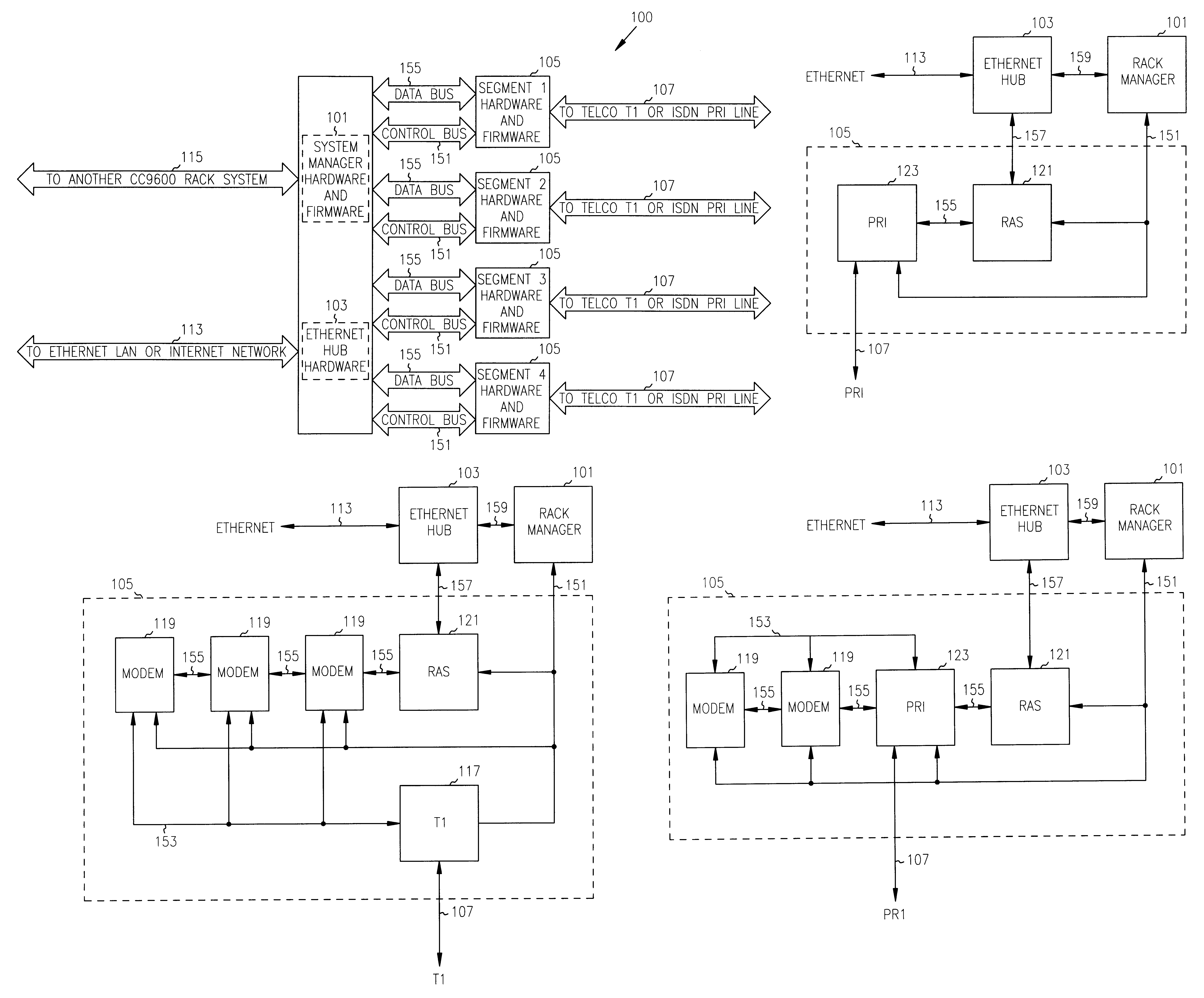
  • Channel bonding in a remote communications server system
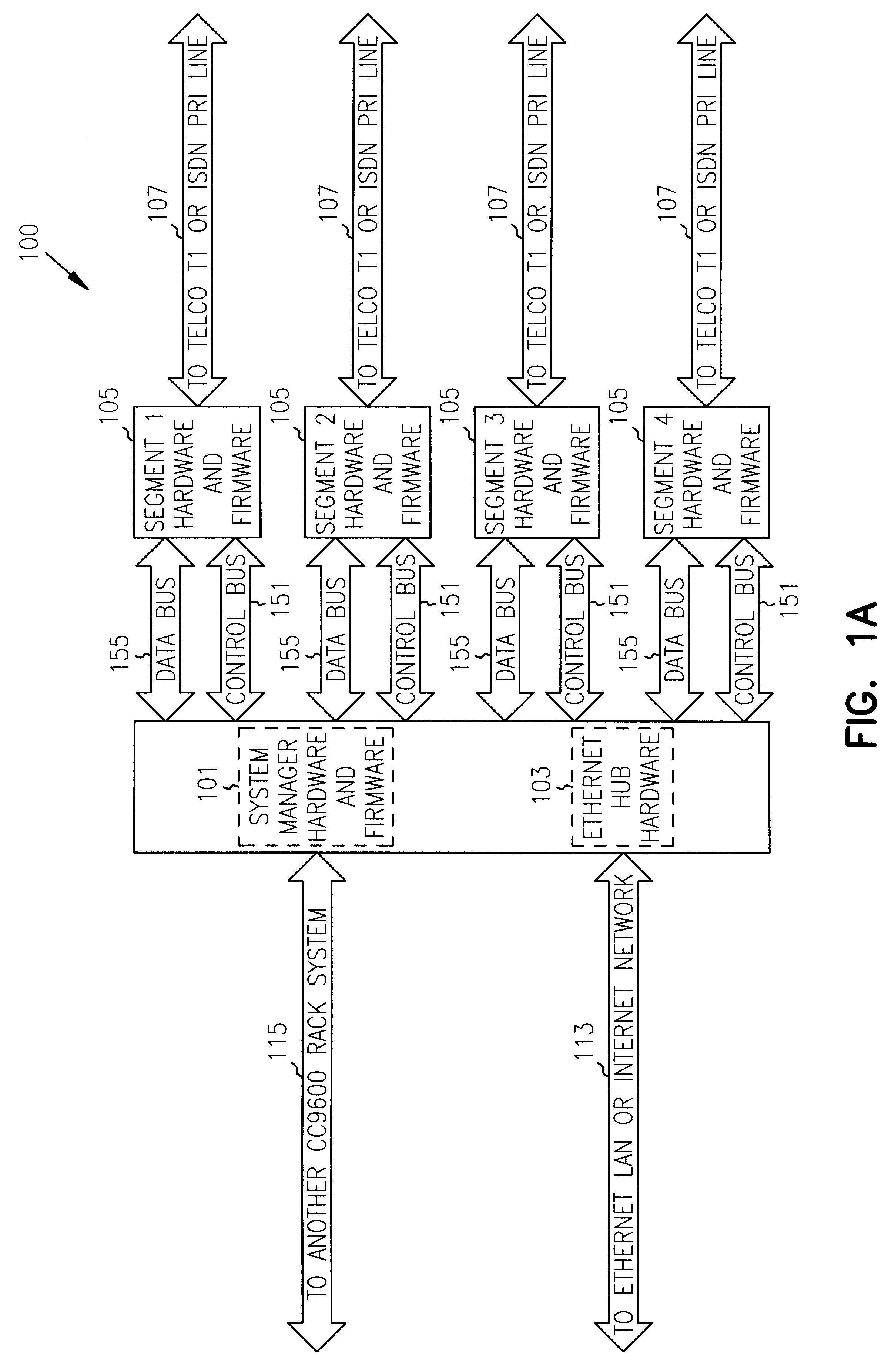
  • Channel bonding in a remote communications server system
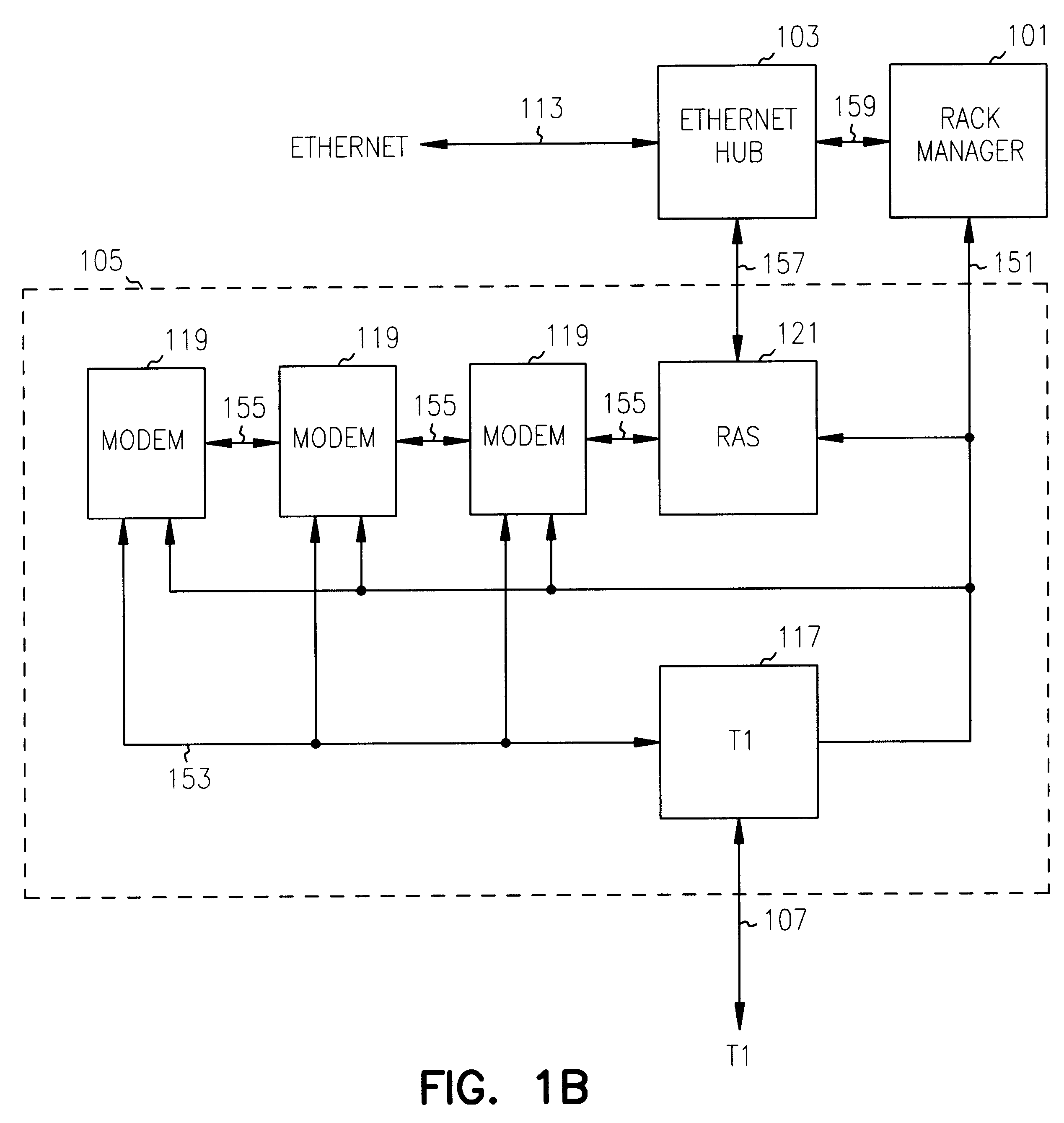
  • Channel bonding in a remote communications server system

Examples


Embodiment Construction

In the following detailed description of the embodiments, reference is made to the accompanying drawings which form a part hereof, and in which is shown by way of illustration specific embodiments in which the invention may be practiced. These embodiments are described in sufficient detail to enable those skilled in the art to practice the invention, and it is to be understood that other embodiments may be utilized and that structural, logical and electrical changes may be made without departing from the spirit and scope of the present inventions. The following detailed description is, therefore, not to be taken in a limiting sense, and the scope of the present inventions is defined only by the appended claims.

The same reference number may used throughout the application to refer to an identical component which appears in multiple Figures. Signals and connections may be referred to by the same reference number or label when the actual meaning will be clear from its use in the contex...


PUM


Abstract

A remote communications server system enables multiple remote users simultaneous access to a network through a segmented design that distributes the processing of the connections among a combination of buses and processors. The system coordinates a plurality of independent communications links bonded together into a single channel to create a virtual connection to the network having a bandwidth greater than the individual links. The system supports a mixture of physical and multiplexed communication links and allows the intermixing of different types of links in a bonded channel. The system is scalable in that segments can be added as needed and the number of lines handled by a segment can be increased.

Description

The present invention is related to data communications and in particular to data communications between multiple dial-up connections and a network.COPYRIGHT NOTICE / PERMISSIONA portion of the disclosure of this patent document contains material which is subject to copyright protection. The copyright owner has no objection to the facsimile reproduction by anyone of the patent document or the patent disclosure as it appears in the Patent and Trademark Office patent file or records, but otherwise reserves all copyright rights whatsoever. The following notice applies to the software and data as described below and in the drawing hereto: Copyright.COPYRGT. 1997, Multi-Tech Systems, Incorporated, All Rights Reserved.Previously, Internet service providers (ISPs) supported multiple simultaneous connections between the Internet and users dialing into the ISP by deploying many modems connected to multiple telephone lines. Each dial-in user connects to a particular modem which is in turn conne...

Claims


Application Information

Patent Timeline
Patent Type & Authority Patents(United States)
IPC IPC(8): H04L12/56H04Q11/04
CPCH04L49/351H04Q11/0478H04L2012/5618
Inventor HONG, KEVINBHAT, DAMODARSUNDARRAAJAN, NARASIMHANMUGULAVALLI, SATISH
Owner MULTI TECH SYST
Learn More