
Parallel and shared parallel analog-to-digital conversion for digital imaging

a digital imaging and parallel technology, applied in analogue/digital conversion, transmission systems, instruments, etc., can solve the problems of requiring more time for successful approximation, affecting the conversion speed of digital imaging, and requiring a lot of time for both types of converters to achieve the effect of increasing the conversion rate, and reducing the conversion rate of digital imaging

Inactive Publication Date: 2003-05-06
MURPHY CHARLES DOUGLAS
View PDF23 Cites 40 Cited by
  • Summary
  • Abstract
  • Description
  • Claims
  • Application Information

AI Technical Summary

Problems solved by technology

While a flash converter is fast, it is also very costly, particularly as the number of bits of precision increases.
However, successive approximation requires more time.
Dual-slope and multi-slope conversion techniques are precise, but quite slow.
However, both types of converters are much slower than successive-approximation and flash converters.
On the other hand, using parallel A / D converters may increase the cost of the conversions.
For example, 100 A / D converters implemented on a chip might require a large amount of chip space and might consume a large amount of power.
However, this may result in a reduction of the "fill factor" of the array.
The processing circuitry is not itself responsive to incident energy, so space it uses on the chip may reduce the space available to the responsive sensor elements.

Method used


Image

  • Parallel and shared parallel analog-to-digital conversion for digital imaging
  • Parallel and shared parallel analog-to-digital conversion for digital imaging
  • Parallel and shared parallel analog-to-digital conversion for digital imaging

Examples


Embodiment Construction

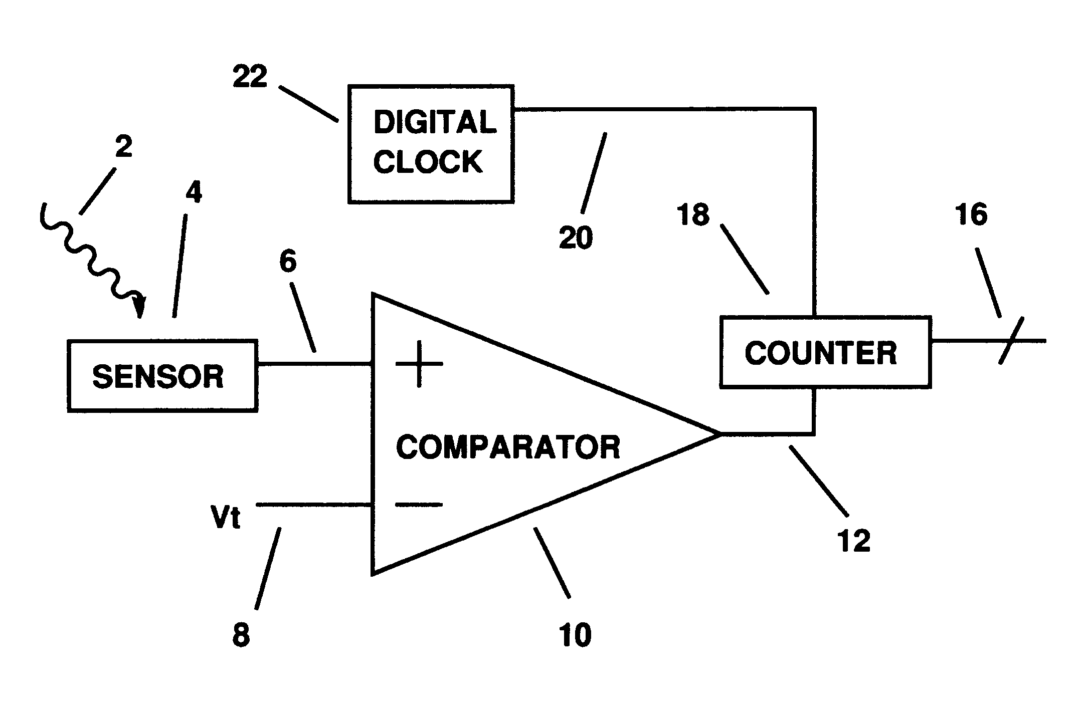
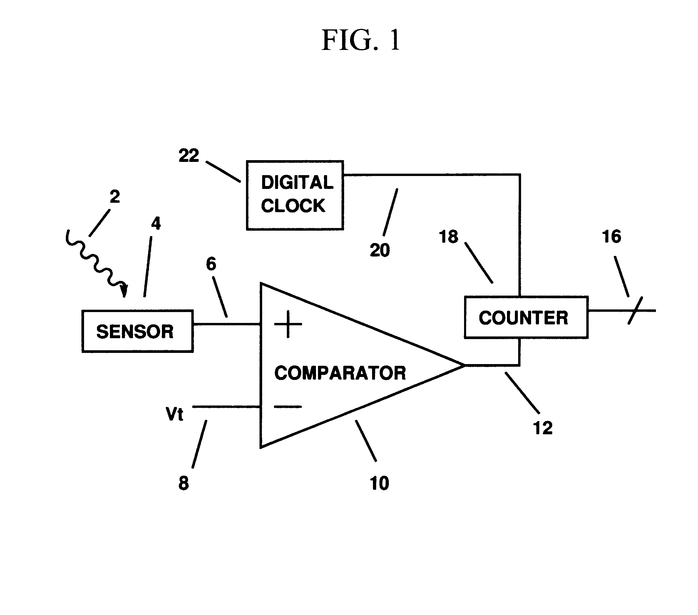
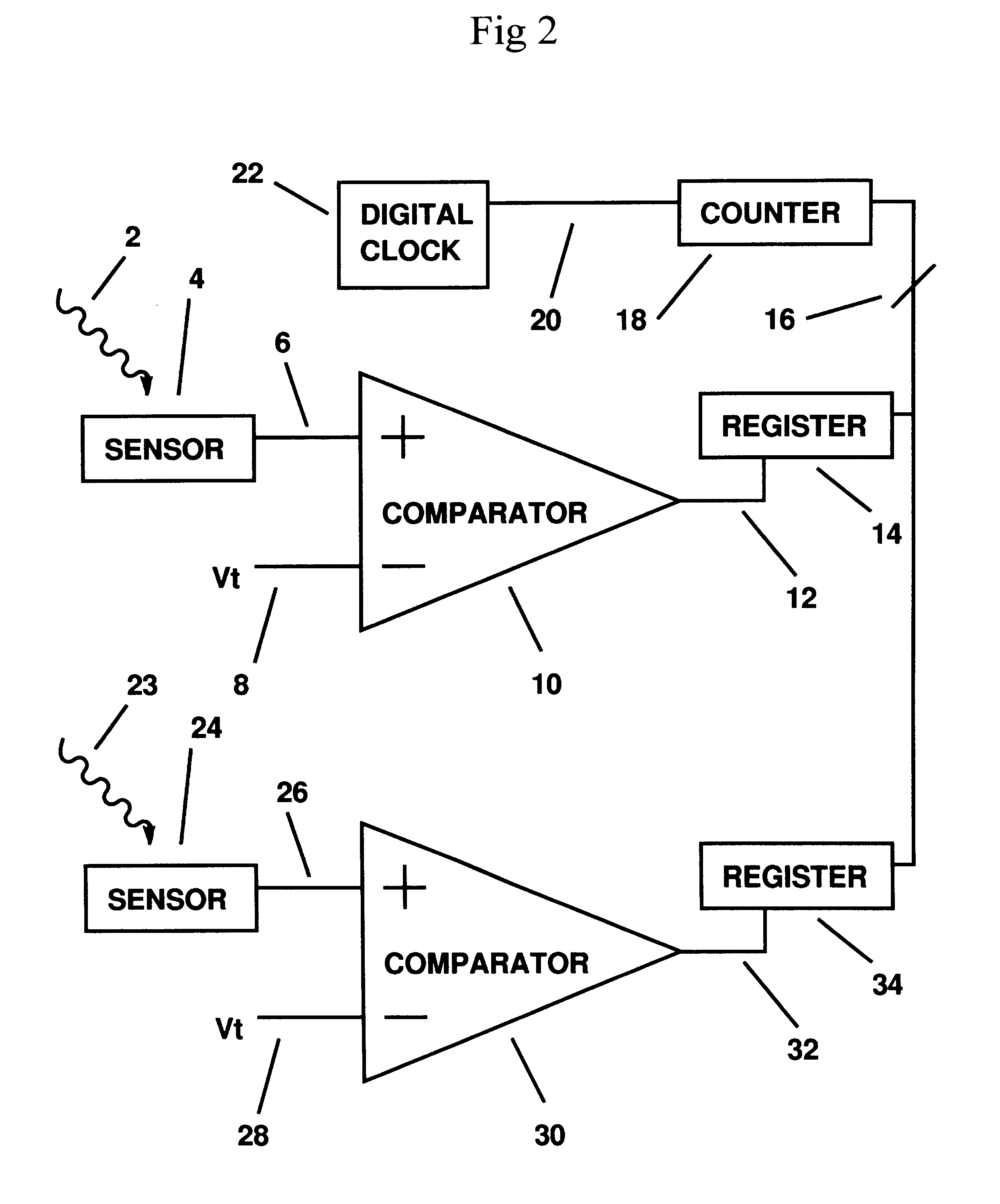
The preferred embodiment of the present invention as described in claim 1 is a machine used for digital image acquisition, comprising a first counter which provides a first count and a first sensor which provides a first sensor output signal. The preferred embodiment includes means for causing the first count to change as a function of time and means for generating a first sensor output signal level change. The preferred embodiment also includes means for detecting when the first sensor output signal level change reaches a first threshold level, and means for measuring a first elapsed count of the first count which is indicative of the time required for the first sensor output signal level change to reach the first threshold level.

In other words, the preferred embodiment of the invention measures the time required for the first sensor output signal level to change by an amount equal to the first threshold level. The first counter keeps track of time via the first count, which might ...


PUM


Abstract

A machine used for acquisition of digital images. A counter tracks the elapsed time since the beginning of image acquisition. When an analog sensor output changes by a pre-set amount, the count is stored as the digital number value representing the sensor output. This eliminates the need for a traditional analog-to-digital (A / D) conversion of the sensor output. In an array of sensors, the circuitry of the invention is simple enough to enable massively parallel A / D conversion. The invention can be implemented in an array using a separate counter for each sensor, but it is also possible to reduce costs by sharing counters among the sensors.

Description

Description of Prior ArtA digital image is often acquired using an array of sensors. At the beginning of image acquisition, the sensors are initialized to known states, and then exposed to incident energy. During the exposure time, the sensors respond to incident energy by changing a sensor parameter. Possible variable sensor parameters include electrical, chemical, and optical properties.Two important digital imaging technologies are charge-coupled device (CCD) arrays and CMOS image sensor arrays. In both of these technologies, the sensor parameters that change in response to incident energy are electrical, either voltage levels or current levels.CCD array technology is older than CMOS sensor array technology. Typically, the CCD sensors are fabricated in a rectangular array comprising rows and columns. The various CCD sensors acquire differing amounts of charge in response to differing amounts of incident energy. At the end of the exposure time, the charge values along one edge of ...

Claims


Application Information

Patent Timeline
IPC IPC(8): H03M1/12H03M1/50
CPCH03M1/50H03M1/123H04N25/772
Inventor MURPHY, CHARLES DOUGLAS
Owner MURPHY CHARLES DOUGLAS
Learn More