Eureka AIR delivers breakthrough ideas for toughest innovation challenges, trusted by R&D personnel around the world.

Computer cabinet design

Inactive Publication Date: 2003-04-29
ENG EQUIP & SERVICE
View PDF30 Cites 218 Cited by
  • Summary
  • Abstract
  • Description
  • Claims
  • Application Information

AI Technical Summary

Benefits of technology

It is an object of the present invention to avoid the necessity of custom cutting of floor tiles to accommodate equipment cabinets.
Still another object is to provide a method of field adjusting the wireway openings so that a cabinet can sit empty without wasting cooling airflow or static pressure, as the wireways remain closed while allowing easy field adjustments for wire and airflow once electronic equipment is installed into the cabinet.

Problems solved by technology

Cooling can also be provided by overhead ducts, but with the degree of cooling required for cabinets containing equipment that creates high temperatures, the room itself would be far too cool for comfort.
Also, the damper is fail safe; that is, if the screws, plugs, etc. holding the damper in a fully closed or partially open position, the damper fully opens and the equipment will not overheat.
Further, the hardware employed is captive hardware such that only broken parts can fall in the cabinet.

Method used


Image

  • Computer cabinet design
  • Computer cabinet design
  • Computer cabinet design

Examples


Embodiment Construction

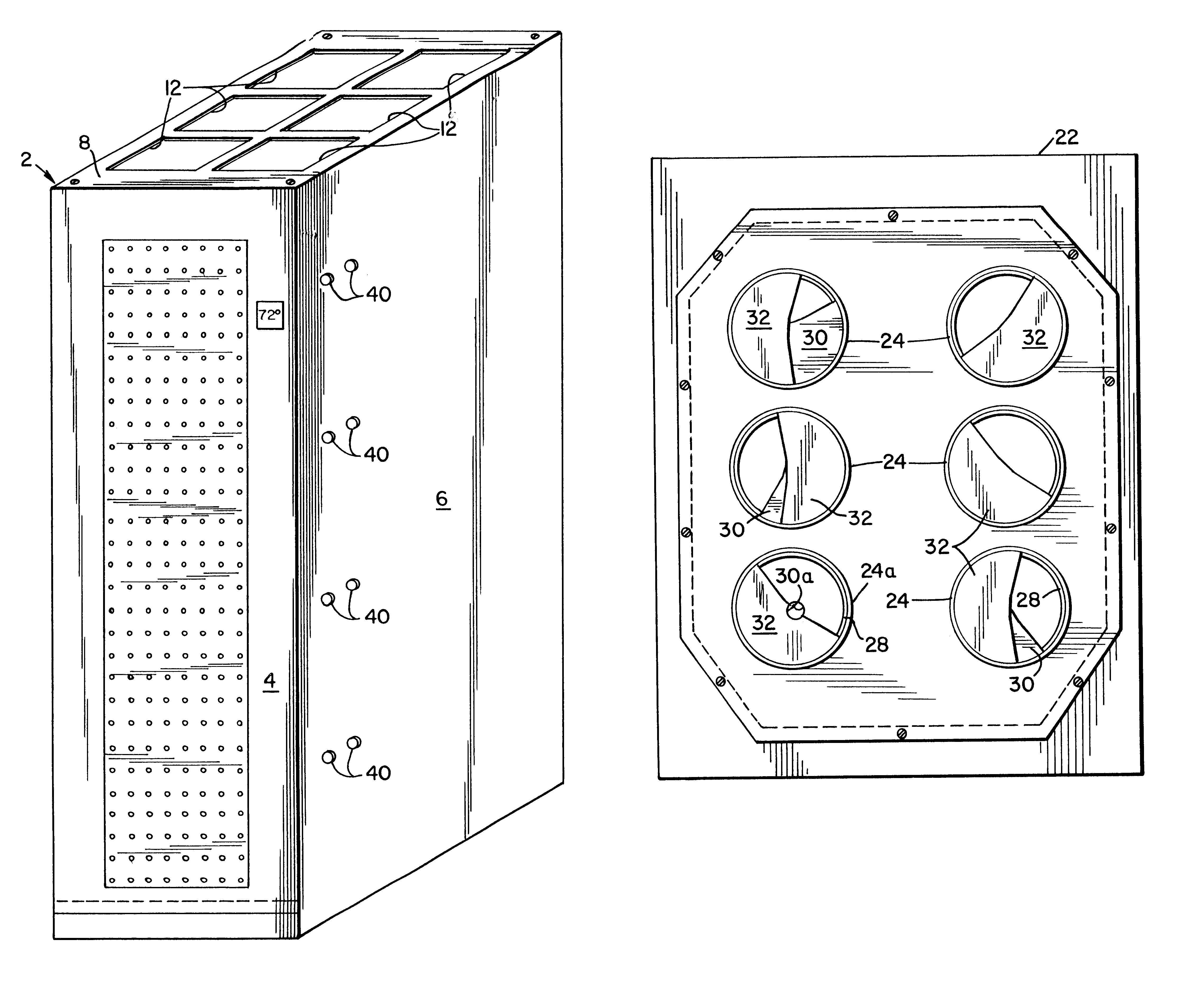
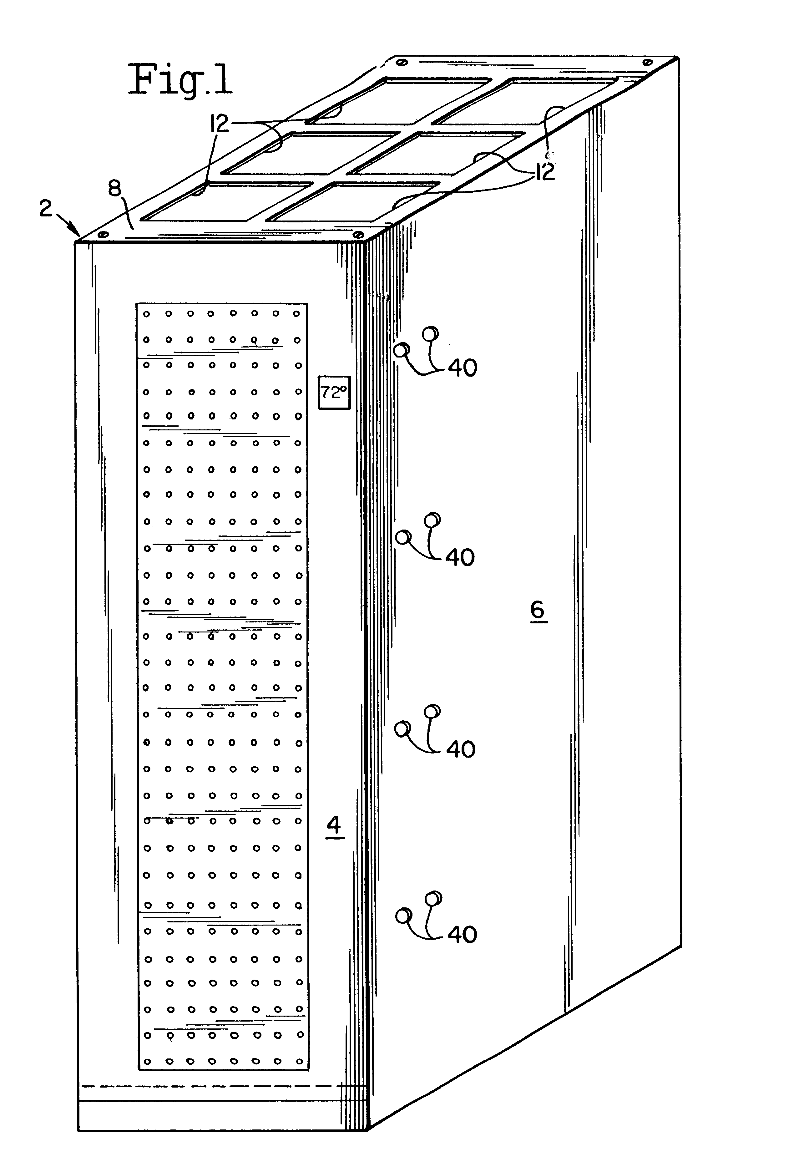
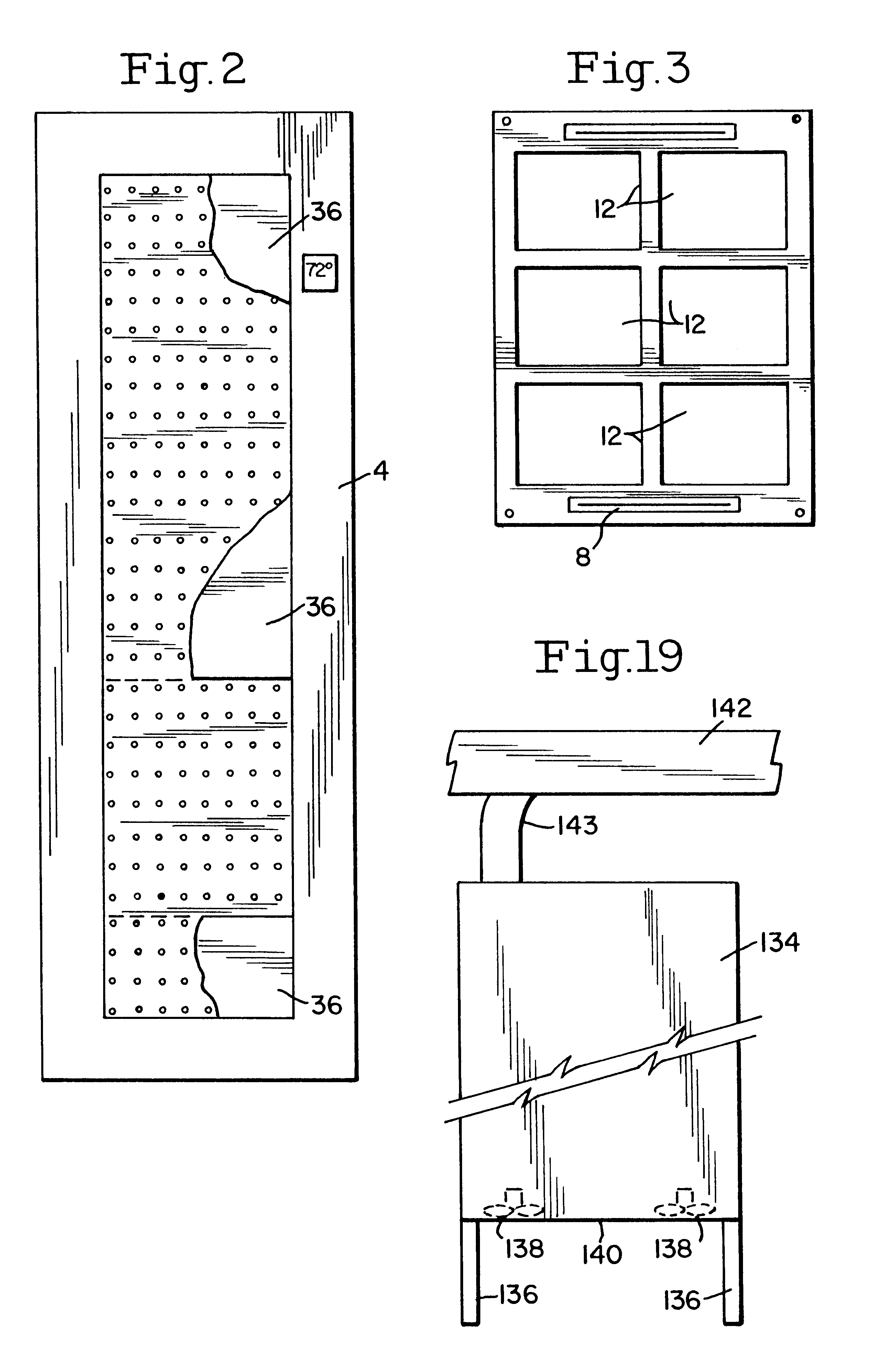
Referring now to FIGS. 1 and 2 of the accompanying drawings, a cabinet 2 has a highly perforated front door 4, side walls 6, only one of which is illustrated, and a back wall also not illustrated, a top wall 8, and a bottom wall 22 illustrated in FIG. 5. It is to be noted that the back panel and in a stand alone environment the side panels may also be highly perforated.

The top wall 8 has at least one or a number of openings 12 to receive panels that may be highly perforated; panel 14FIG. 4A, solid panel 16, FIG. 4B or have a fan bearing panels 20 having a fan 18 mounted therein, FIG. 4C. FIG. 4D a top view of a variable opening panel grommet in the top wall to receive wires, if necessary.

The structure of top wall 8 is illustrated in greater detail in FIG. 3, each opening 12 being approximately 8 1 / 2" deep.times.11 1 / 8" wide in one embodiment of the invention. The highly perforated panel 14 is employed when a fan or fans are not used, panel 16 is used when a fan (or fans) is operatin...


PUM


Abstract

Cabinets or enclosures are provided having heat generating elements stored therein cooled by locating the cabinets on tiles of an elevated floor having cool air provided under the tiles, the cabinets having variable size openings in their bottom surface located over openings in the tiles, openings in the top surface of the cabinets, which openings may have fans located in the openings, highly perforated shelves and a highly perforated front door. By controlling the size of the various openings, and the number, if any, of fans and air flow through the door the temperature in the cabinet may be controlled. A number of cabinets may be located side-by-side with side walls in contact and with wires introduced into one cabinet from under the tiles through an opening in its bottom wall being passed from cabinet-to-cabinet through aligned openings in the side walls of the cabinets. The air flow within the cabinets may be reversed in air conditioned rooms not having cooling air under the floor on which the cabinet is situated.

Description

The present invention relates to cooling of equipment in cabinets and more particularly to integrate the cabinet cooling into a raised floor or overhead cooling system.It has been found that cabinet cooling systems that are not integrated with a fault tolerant, concurrently maintainable and transparently expandable design of a raised floor or overhead cooling system cannot reasonably control overheating of equipment. The heat produced in some of the higher technology systems exceeds the capacity of systems currently available resulting in damage to high-tech computers and peripheral equipment.Often, expensive, quality uninterruptable power systems (UPS) are installed for both the computer systems and cabinet fan powered cooling assemblies. Existing cabinet cooling technologies, waste available UPS power because methods do not exist to vary the fan energy as a percentage of the power required to cool the critical computer and other electronic equipment installed in the cabinets. Addi...

Claims


Application Information

Patent Timeline
IPC IPC(8): H05K7/20G06F1/18G06F1/20
CPCG06F1/18H05K7/20718G06F1/206G06F1/20
Inventor KOPLIN, EDWARD C.
Owner ENG EQUIP & SERVICE
Why Eureka
Eureka Blog
Learn More