
Capsulorrhexis device

a technology of capsulorrhexis and stent, which is applied in the field of surgical instruments, can solve the problems of radial tear, weak jagged edges, and unpredictable tears of most skilled surgeons

Inactive Publication Date: 2003-04-22
VAN HEUGTEN ANTHONY Y +2
View PDF6 Cites 89 Cited by
  • Summary
  • Abstract
  • Description
  • Claims
  • Application Information

AI Technical Summary

Problems solved by technology

Using any of these methods, even the most skilled surgeons can create unpredictable tears.
Some tears deviate outward and / or inward from the intended circular path and some have jagged edges that are weak and can tear radially during the stresses put onto the capsule during the insertion of the synthetic lens.
Tears that extend within the desired circular shape intrude into the optical zone, impairing vision.
Tears that extend beyond the desired circular shape not only detract from a good surgical result, but they can lead to other serious complications such as a ruptured capsule or a decentered lens.
The problem with this device is that the guiding loop is too large to enter into the eye through a small incision.
In fact, the incision size required is equal to the diameter of the capsulorrhexis, which is not desirable.
The problems associated with these types of devices are that they require the surgeon to manually move the instruments in the desired circular path, resulting not only in imperfect circles, but the motion itself produces damage to surrounding tissue, particularly the endothelium cells (located on the inside of the cornea, and once damaged, will not regenerate).
The problems with this device are that no provision is made for the slicing action required to cut the capsule.
Secondly, there are limitations as to how small it can be made, making it impractical for use in the ever-decreasing incision sizes the surgery demands.
The problem with this device is that it has many moving parts, making it difficult to manufacture and to make it small enough to fit within the very small incisions made in modern cataract surgery.
Furthermore, instruments with complex moving parts are difficult to clean and sterilize between each use due to body fluids becoming trapped in small cavities.

Method used


Image

  • Capsulorrhexis device
  • Capsulorrhexis device
  • Capsulorrhexis device

Examples


Embodiment Construction

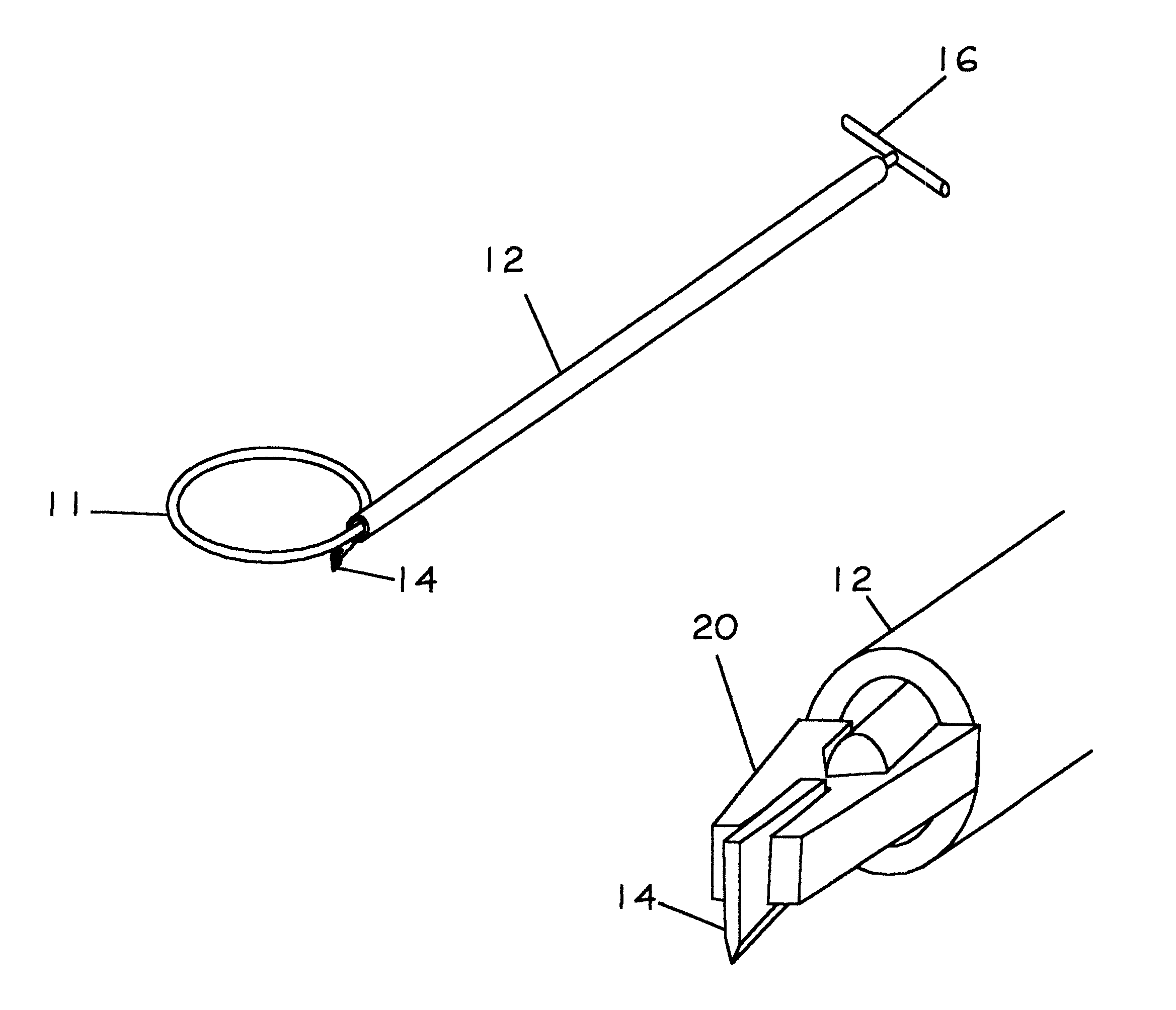
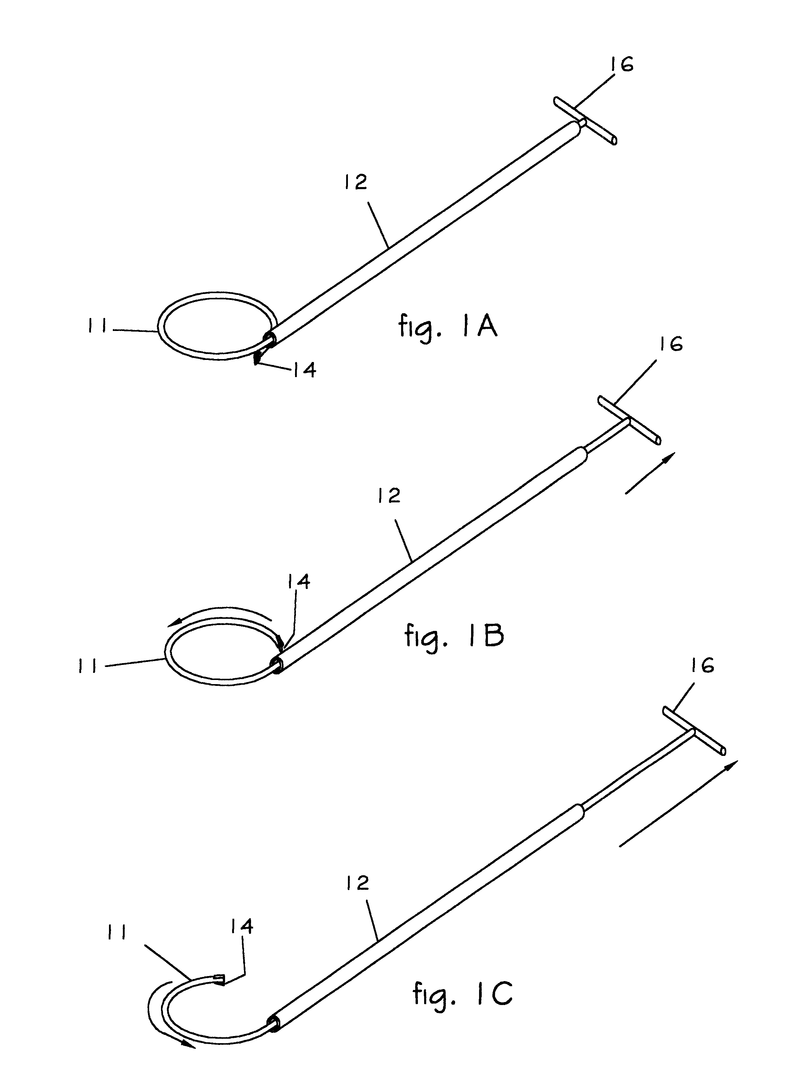
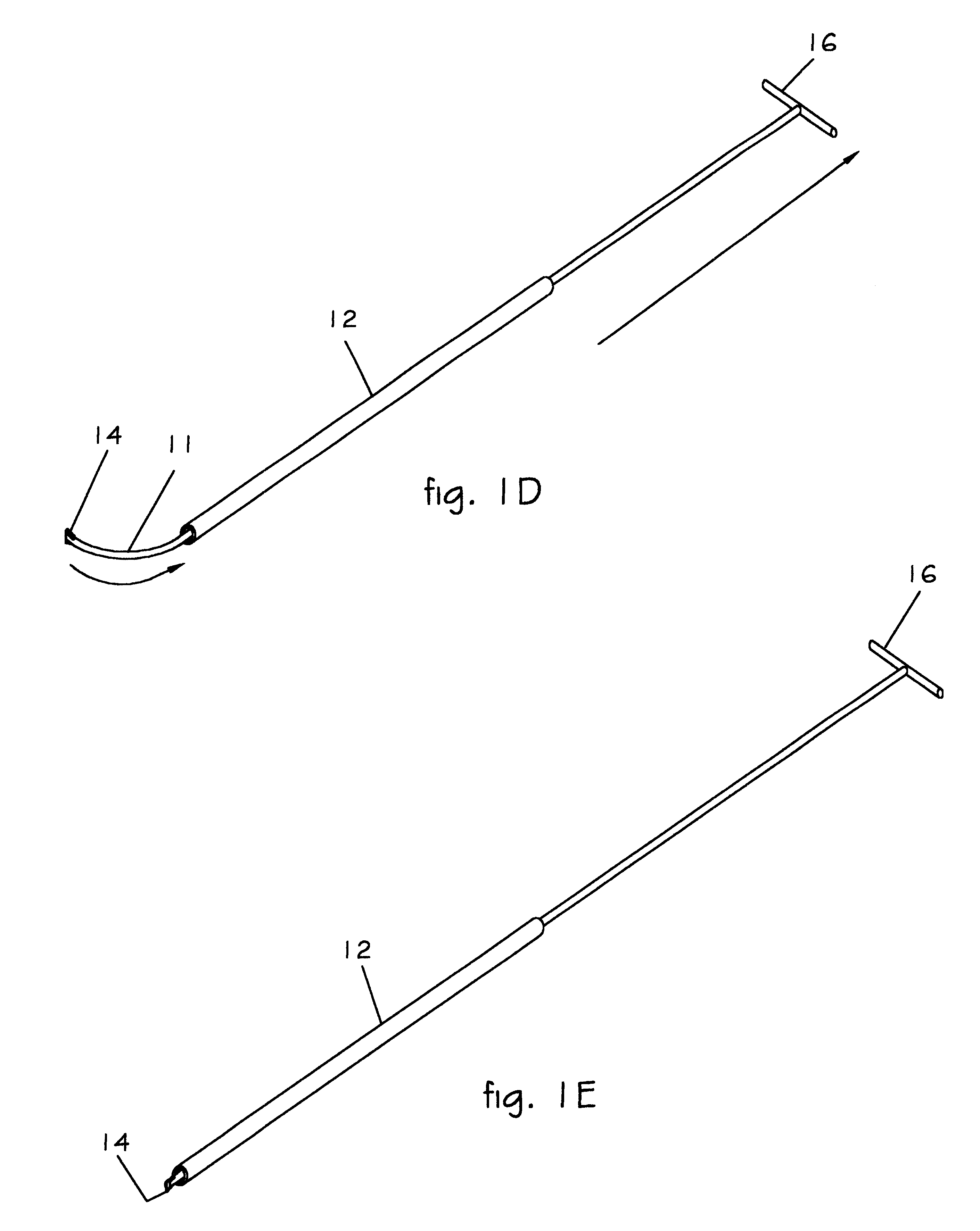
A preferred embodiment of the present invention is illustrated in FIGS. 1A thru 1E, 2B, 6 and 7. A super-elastic rod inner member 11 has a circular loop that can repeatably be confined into a straight shape, and when released, returns to its circular loop shape without losing the memory of that circular shape. A slot is cut into the distal tip of the rod 11, and a blade 14 is mounted into the slot. The straight section of the rod 11 is positioned inside of a tubular outer member 12.

When the circular loop section of the rod 11 is retracted inside of the tube 12, the circular loop section straightens to conform to the inside shape of the tube 12. The width of the device in this position is now considerably less than the width of the circular loop, allowing insertion and withdrawal through a small incision.

Once inserted into an eye, the loop section of the rod 11 is expelled from the tube 12, and the loop reforms into its natural, circular loop shape. As the rod 11 is again retracted b...


PUM


Abstract

A surgical instrument that creates a circular cut 42 of almost any diameter in the lens capsule 50 of the eye, yet its entire diameter is less than 1 mm when inserted into the eye. A cutting edge 14 is affixed to the distal tip of a super-elastic rod 11 with its distal end formed into a circular loop. The circular loop is first retracted inside of an outer tube member 12, and then the tube 12 is inserted into the eye. The loop is then expelled from the tube 12, allowing the loop to reform inside of the eye. As the loop is retracted back into the tube 12, the cutting edge 14 follows the circular path of the loop, cutting a circular opening (a capsulorrhexis) 42, into the lens capsule 50.

Description

BACKGROUND--FIELD OF THE INVENTIONThe present invention relates generally to surgical instruments, and more particularly to providing an instrument for forming a circular opening in the lens capsule of the eye during cataract surgery.BACKGROUND--DESCRIPTION OF PRIOR ARTIn some people, particularly elderly people, the lens inside of the eye grows cloudy. This is referred to as a cataract. The common method of correcting this condition is to remove the natural cloudy lens and replace it with a clear synthetic lens. The natural lens is shaped like a flattened sphere, approximately 9 mm in diameter, and is contained within a capsule. The capsule is suspended radially by countless fine strings, or zonule ligaments, which are connected from the outer periphery of the capsule to the inside surface of the eyeball. In cataract surgery, an incision is made into the eye, and then a circular opening is cut into the lens capsule, typically 6 mm in diameter. (This circular opening cut into the ca...

Claims


Application Information

Patent Timeline
IPC IPC(8): A61F9/007
CPCA61F9/00754
Inventor VAN HEUGTEN, ANTHONY Y.VAN HEUGTEN, SUSAN L.VAN HEUGTEN, CHRISTINA J.
Owner VAN HEUGTEN ANTHONY Y
Learn More