
Optical disk and optical disk apparatus

a technology which is applied in the field of optical disk and optical disk apparatus, can solve the problems of difficult to read out control information in a short time, redundancy increases in the rewritable track area, and complex circuit configuration for detecting whether the pit patterns are matched

Inactive Publication Date: 2003-04-15
PANASONIC CORP
View PDF15 Cites 18 Cited by
  • Summary
  • Abstract
  • Description
  • Claims
  • Application Information

AI Technical Summary

Benefits of technology

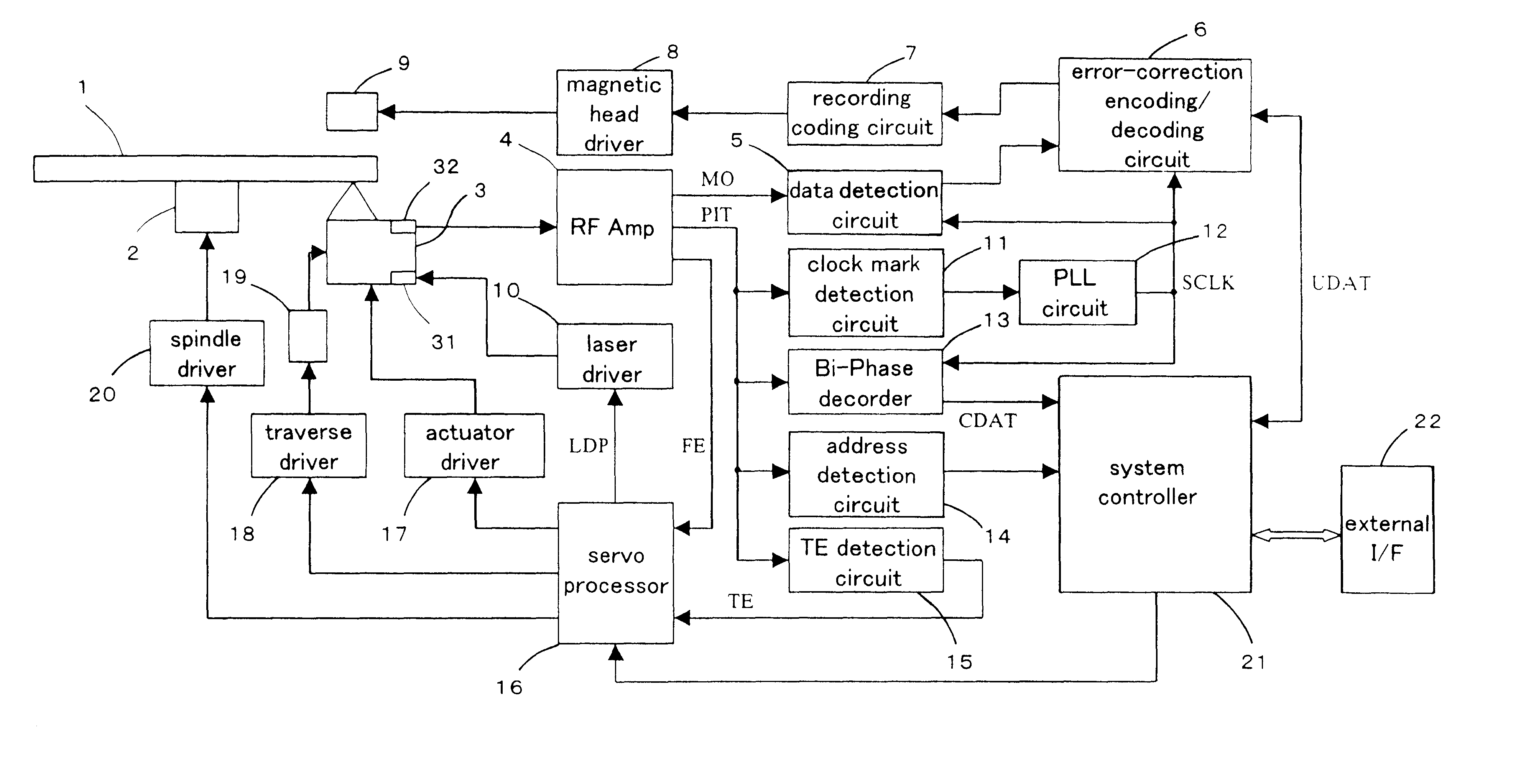
Therefore, it is an object of the present invention to provide an optical disc in a sample servo format applicable to high density recording, in which a control track area is formed without reducing format efficiency of a rewritable track area, and also to provide an optical disc device that can read out control information in a short time with a simple circuit configuration.
According to this configuration, the emboss prepits of the control data are arranged identically in the radial direction, so that the optical disc device can read out the control data only by performing a focus control, without performing a tracking control of tracing the tracks precisely. As a result, the readout of the control data can be completed in a short time.

Problems solved by technology

However, the problem with the optical disc that specifies the servo area by confirming that the pit patterns reproduced by the optical disc drive match with each other for the three pits including the identification mark of different recording positions depending on the identification information of the segment and the two wobble pits, is that redundancy increases in a rewritable track area, which is a user area enabling writing.
Therefore, the circuit configuration for detecting whether the pit patterns are matched becomes complicated.
At the same time, it takes time until the servo clock comes to a phase lock, and thus it is difficult to read out the control information in a short time.
Furthermore, in the case of the above-mentioned optical disc, in which not only the wobbles containing the synchronization signals and the control information or the address information independent of each other but also the clock mark are formed in the guide groove of the respective tracks, the optical disc is not only incompatible with the sample servo format but also difficult to be applied to high density recording by narrowing the track pitch.

Method used


Image

  • Optical disk and optical disk apparatus
  • Optical disk and optical disk apparatus
  • Optical disk and optical disk apparatus

Examples


Embodiment Construction

In the following, a preferable embodiment of the present invention will be explained based on the drawings. In addition, an optical disc used in the embodiment of the present invention is a magneto-optical disc in a sample servo format applicable to rotational systems of both the ZCLV system and the ZCAV system mentioned above.

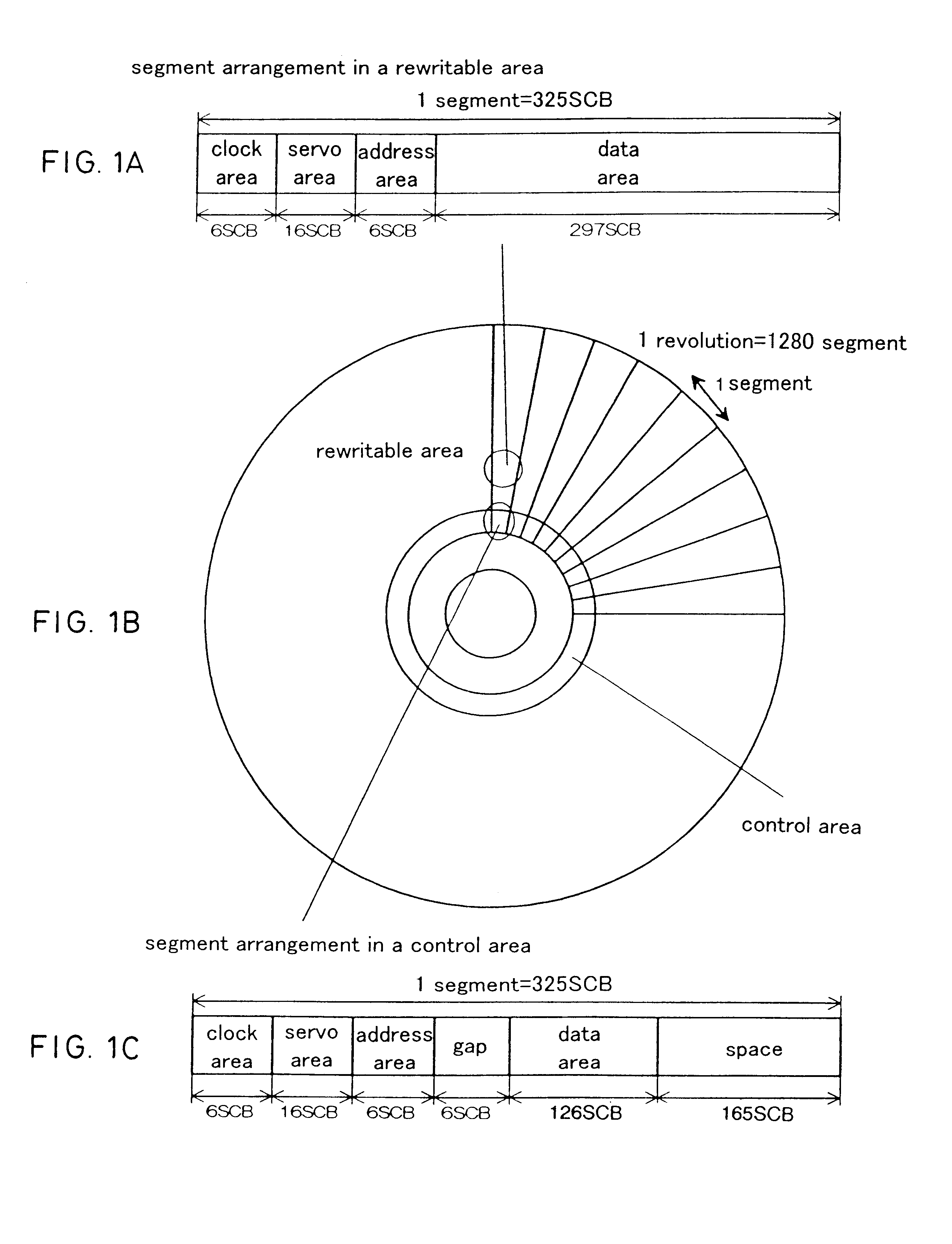
FIG. 1(a) to FIG. 1(c) are the structural views of segments in an optical disc according to an embodiment of the present invention. As shown in FIG. 1(b), a control track area where control data are recorded is provided in the vicinity of an inner circumferential end of the optical disc. The control data include, for example, generation information of media, vendor information of media, information of recording reproduction characteristics of a disc (laser power etc.), format information and so forth. Furthermore, a rewritable track area where user data are recorded and reproduced as magneto-optical signals is provided outside the control track area, covering ...


PUM


Abstract

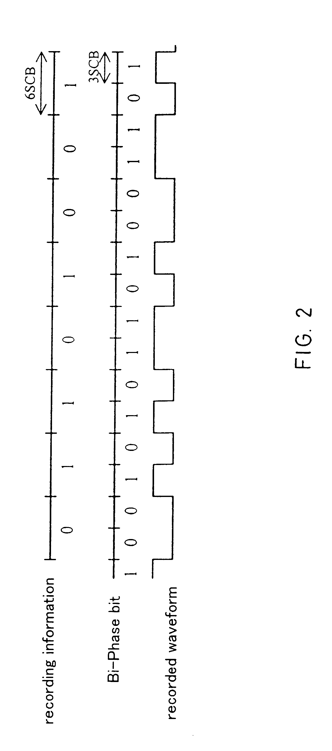
An optical disc in a sample servo format applicable to high density recording in which a control track area is formed without reducing format efficiency of a rewritable track area and an optical disc device that can read out control information in a short time with a simple circuit configuration are provided. For this purpose, in the optical disc, a space of a predetermined length where emboss prepits do not exist is arranged for each segment in the control track area, following a data area where control data are recorded by emboss prepits as a clock mark, wobble marks and an address mark.

Description

TECHNICAL FIELDThe present invention relates to an optical disc in a sample servo format and an optical disc device.BACKGROUND ARTIn recent years, as media to record information optically, an optical disc, an optical card, an optical tape and so forth are proposed and developed. Among them, the optical disc is drawing attention as a medium that can record and reproduce information in a large capacity and of high density.As for an optical disc capable of recording and reproduction, a magneto-optical (MO) disc is generally known. With regard to the optical disc system for performing recording and reproduction of various data by scanning concentric circular or spiral tracks formed on such an optical disc with a laser beam, corresponding to its rotation system, there are a ZCLV system, which performs recording and reproduction of data by dividing a recording area into zones including a predetermined number of tracks, reducing the number of revolutions in the optical disc stepwise moving...

Claims


Application Information

Patent Timeline
IPC IPC(8): G11B20/14G11B7/00G11B7/09G11B7/007G11B20/10G11B20/12G11B7/005G11B11/00G11B11/105G11B7/004
CPCG11B7/007G11B7/00745G11B7/0938G11B20/10G11B20/12G11B20/1217G11B20/14G11B7/005G11B7/00G11B2220/2525G11B11/10597G11B2020/1232G11B2020/1265G11B2020/1274G11B2020/1287G11B2220/216
Inventor INOUE, TAKASHIUEDA, EIJI
Owner PANASONIC CORP
Learn More