
X-ray photo-taking system, X-ray photo-taken image display method, and storage medium

a technology of x-ray photo-taking and image display, which is applied in the field of x-ray photo-taking system, x-ray photo-taking image display method, and storage medium, can solve the problems of cumbersome inverting each film, difficult to identify the lesion, and difficult to distinguish the side (right or left) and the direction with no marks,

Inactive Publication Date: 2003-04-01
CANON KK
View PDF7 Cites 71 Cited by
  • Summary
  • Abstract
  • Description
  • Claims
  • Application Information

AI Technical Summary

Problems solved by technology

If a lesion is present in a portion where regions overlap each other, it is not easy to identify the lesion in many instances.
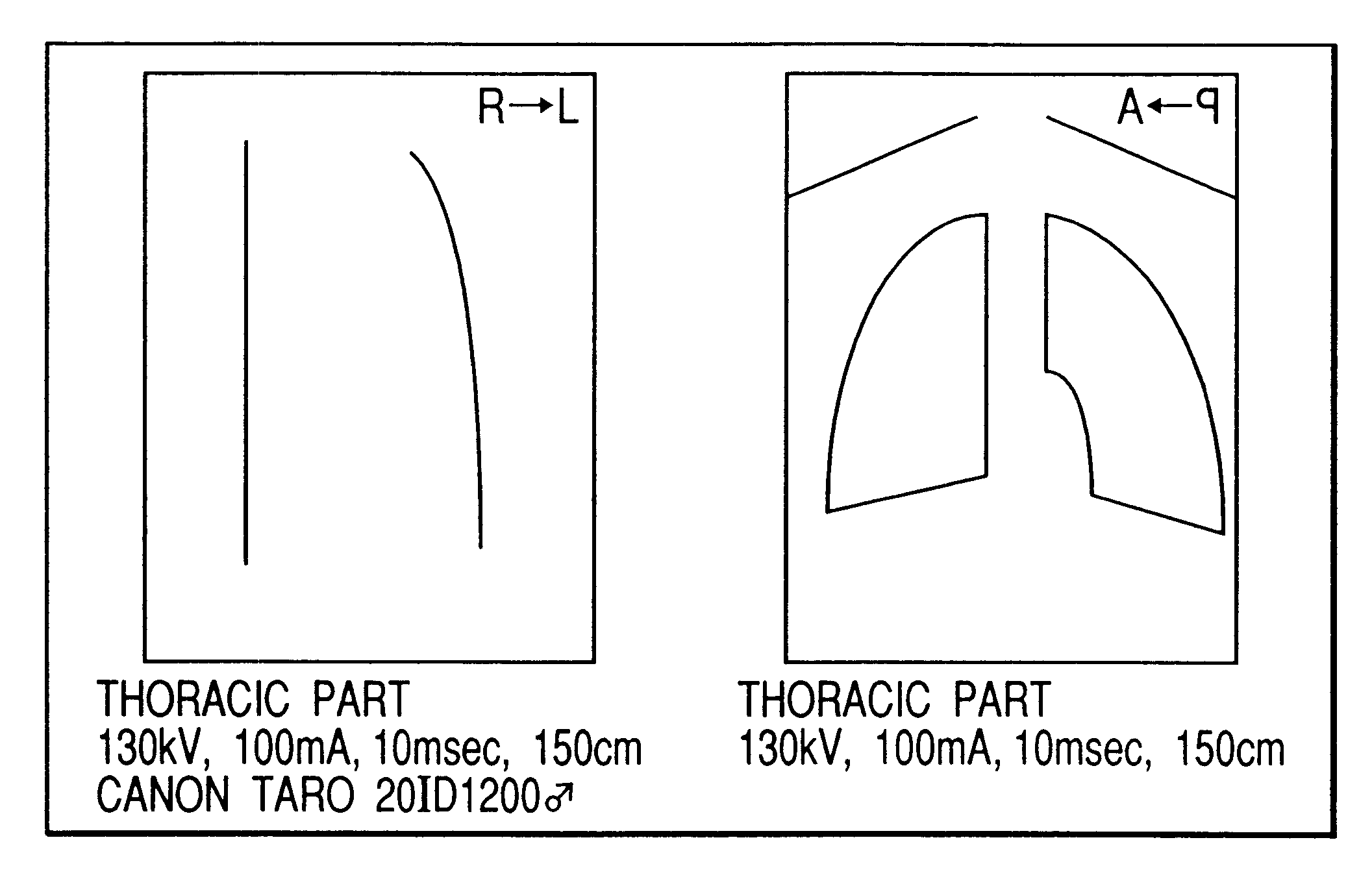
Furthermore, right and left shoulder joints, wrist joints, and limbs are separately photo-taken, so the side (right or left) and the direction are difficult to distinguish with no marks.
When image reading is performed following this procedure, inverting each film is cumbersome if a large number of films are to be interpreted.
In this case, however, although the film need not be inverted, the photo-taking direction and the photo-taking method cannot be immediately identified in comparison to films photo-taken by the X-ray photographing system.
Additionally, when the laterally inverted images are again stored, the direction of X-ray irradiation cannot be immediately determined.
"forearms", "upper arms", "thighbones", and "lower leg bones" are photo-taken in different directions, it is not easy to display the images in appropriate layout and readily understandable form.
However, it is difficult to distinguish between the right and the left and recognize the irradiation direction with only text data.
Additionally, when an image is inverted, the direction of an original image cannot be known.
Furthermore, images of the same region but in different directions cannot be displayed on the same medium with simple operation.

Method used


Image

  • X-ray photo-taking system, X-ray photo-taken image display method, and storage medium
  • X-ray photo-taking system, X-ray photo-taken image display method, and storage medium
  • X-ray photo-taking system, X-ray photo-taken image display method, and storage medium

Examples


first embodiment

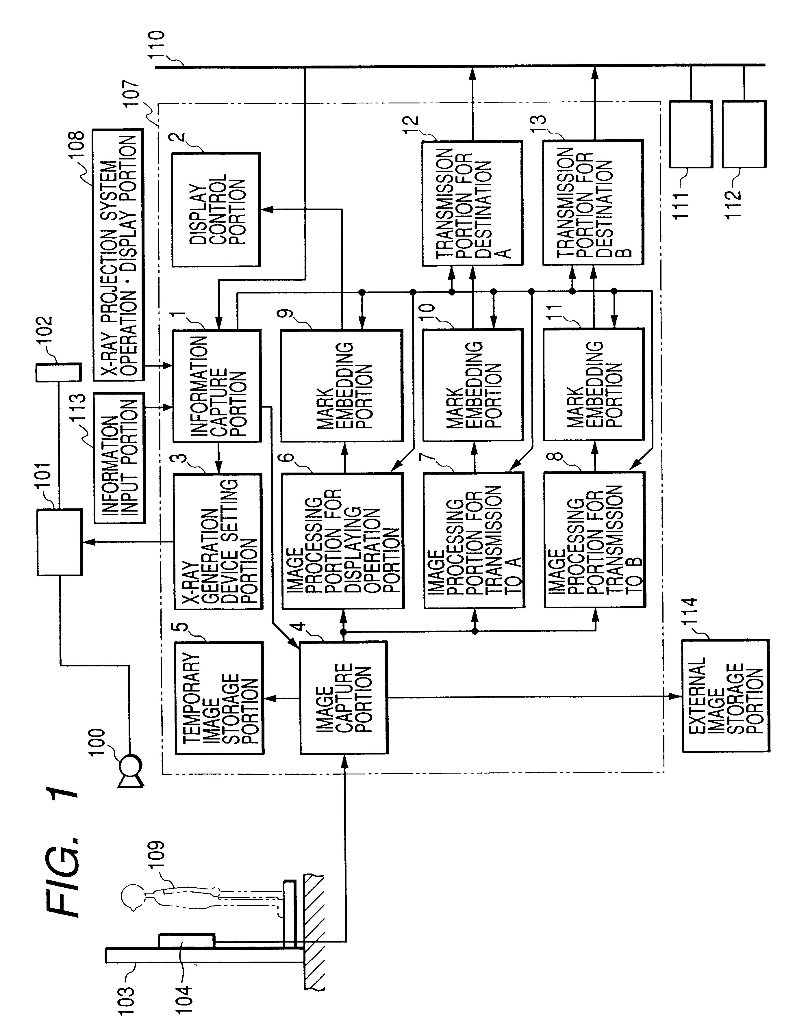
FIG. 1 is a block diagram showing the overall arrangement of an X-ray photo-taking system according to the present invention.

This X-ray photo-taking system according to the first embodiment of the present invention comprises an X-ray tube 100, an X-ray generation device control portion 101, an X-ray generation device operation.display portion 102, a standing position sensor unit 103, a standing position sensor panel 104, an X-ray photo-taking system control portion 107, an X-ray photo-taking system operation.display portion 108, a network 110, a film imager 111, an image server 112, an information input portion 113, and an external image storage portion 114. The X-ray photo-taking system control portion 107 includes an information capture portion 1, a display control portion 2, an X-ray generation device setting portion 3, an image capture portion 4, a temporary image storage portion 5, an image processing portion 6 for displaying operation portion, an image processing portion 7 for...

second embodiment

As in the above first embodiment, an X-ray photo-taking system according to the second embodiment of the present invention comprises an X-ray tube 100, an X-ray generation device control portion 101, an X-ray generation device operation.display portion 102, a standing position sensor unit 103, a standing position sensor panel 104, an X-ray photo-taking system control portion 107, an X-ray photo-taking system operation.display portion 108, a network 110, a film imager 111, an image server 112, an information input portion 113, and an external image storage portion 114. The X-ray photo-taking system control portion 107 includes an information capture portion 1, a display control portion 2, an X-ray generation device setting portion 3, an image capture portion 4, a temporary image storage portion 5, an image processing portion 6 for displaying operation portion, an image processing portion 7 for transmission to A, an image processing portion 8 for transmission to B, mark embedding port...

third embodiment

This third embodiment of the present invention is the same as the above first and second embodiments except that the image format portions 14, 15, and 16 are added to the X-ray photo-taking system control portion 107. When photo-taking of an object to be examined is completed, the image format portions 14, 15, and 16 display the image in a predetermined format by looking up a format table (FIG. 10) that is classified in units of photo-taking regions and is preset. Note that the same reference numerals as in FIG. 1 denote parts having the same functions in FIG. 8, and a detailed description thereof will be omitted.

The characteristic feature of this third embodiment of the present invention is as follows. That is, when photo-taking of the same photo-taking region of one object to be examined is performed a plurality of times as in the case of "chast part front photo-taking and thoracic part side photo-taking, image reading is facilitated by displaying the photo-taken images of the sam...


PUM


Abstract

This invention provides an X-ray photo-taking system, X-ray photo-taken image display method, and storage medium by which an operator can readily understand the position (right, left, or center) of a photo-taking region of an object to be examined, the X-ray irradiation direction, and the photo-taking attitude only by monitoring an X-ray image, and by which text information is narrowed down to patient information and photo-taking information to make these pieces of information easy to see. The system includes an information capture portion for symbolizing the direction of an object to be examined during photo-taking, the photo-taking direction, the position of a photo-taking region, and the photo-taking attitude, a mark embedding portion for embedding a mark in a portion of an image, a display control portion for displaying the X-ray photo-taken image in which the mark is embedded by the mark embedding portion, and a transmission portion for transmitting the X-ray photo-taken image in which the mark is embedded by the mark embedding portion to a network.

Description

1. Field of the InventionThe present invention relates to an X-ray photo-taking system, X-ray photo-taken image display method, and storage medium for obtaining an X-ray transmission image of an object to be examined and, more particularly, to an X-ray photo-taking system, X-ray photo-taken image display method, and storage medium suited to display an X-ray photo-taken image after photo-taking.2. Related Background ArtConventionally, an X-ray photographing system combining an intensifying screen and a film in an X-ray detection portion has been extensively used as an X-ray photo-taking apparatus for medical diagnostic purposes. In this system, when X-rays transmitted through an object to be examined enter the intensifying screen, a phosphor contained in this intensifying screen absorbs the X-ray energy to emit fluorescence. This fluorescence exposes the X-ray film to form a radiation image as a latent image on the film. This X-ray image is visualized by developing and fixing the fil...

Claims


Application Information

Patent Timeline
IPC IPC(8): A61B6/00H04N1/32
CPCA61B6/00A61B6/4233A61B6/463A61B6/465H04N1/32144A61B6/467A61B6/468A61B6/4494H04N2201/0079H04N2201/3205H04N2201/3226H04N2201/3252H04N2201/3278A61B6/469
Inventor TAKASAWA, TORU
Owner CANON KK
Learn More