
Hot plug control of MP based computer system

Inactive Publication Date: 2003-03-18
IBM CORP
View PDF18 Cites 35 Cited by
  • Summary
  • Abstract
  • Description
  • Claims
  • Application Information

AI Technical Summary

Benefits of technology

It is another object of the present invention to provide such a method that allows a wide variety of computer components to be upgraded or serviced, without interrupting system operation.
It is yet another object of the present invention to provide such a method that carefully controls and monitors the power supplied to any such hot-pluggable devices, individually.

Problems solved by technology

Expansion buses such as the ISA and PCI buses were originally very limited, in that the entire computer system had to be powered down before any peripheral device could be added to or removed from a PCI adaptor slot, and then powered up again (rebooted) to properly initialize the operating system and any new peripheral device.
Furthermore, components such as VRMs are generally not removable, and any replacement requires field service by a qualified engineer, since the VRM is hardwired into the system.
Unfortunately, a user may not only want to add another PCI device, but further might want to replace a defective processor, memory bank, or VRM, without service interruption.
For many computer systems (particularly large servers used in a client-server network), there may be hundreds of users connected to it, and the down time required to perform such a service operation can be extremely expensive.
One problem in providing such hot-pluggable devices relates to control of the voltages and currents involved.
Individual control must be maintained for the power characteristics of each hot-pluggable device, but presently available power supply designs are incapable of providing such control.

Method used


Image

  • Hot plug control of MP based computer system
  • Hot plug control of MP based computer system
  • Hot plug control of MP based computer system

Examples


Embodiment Construction

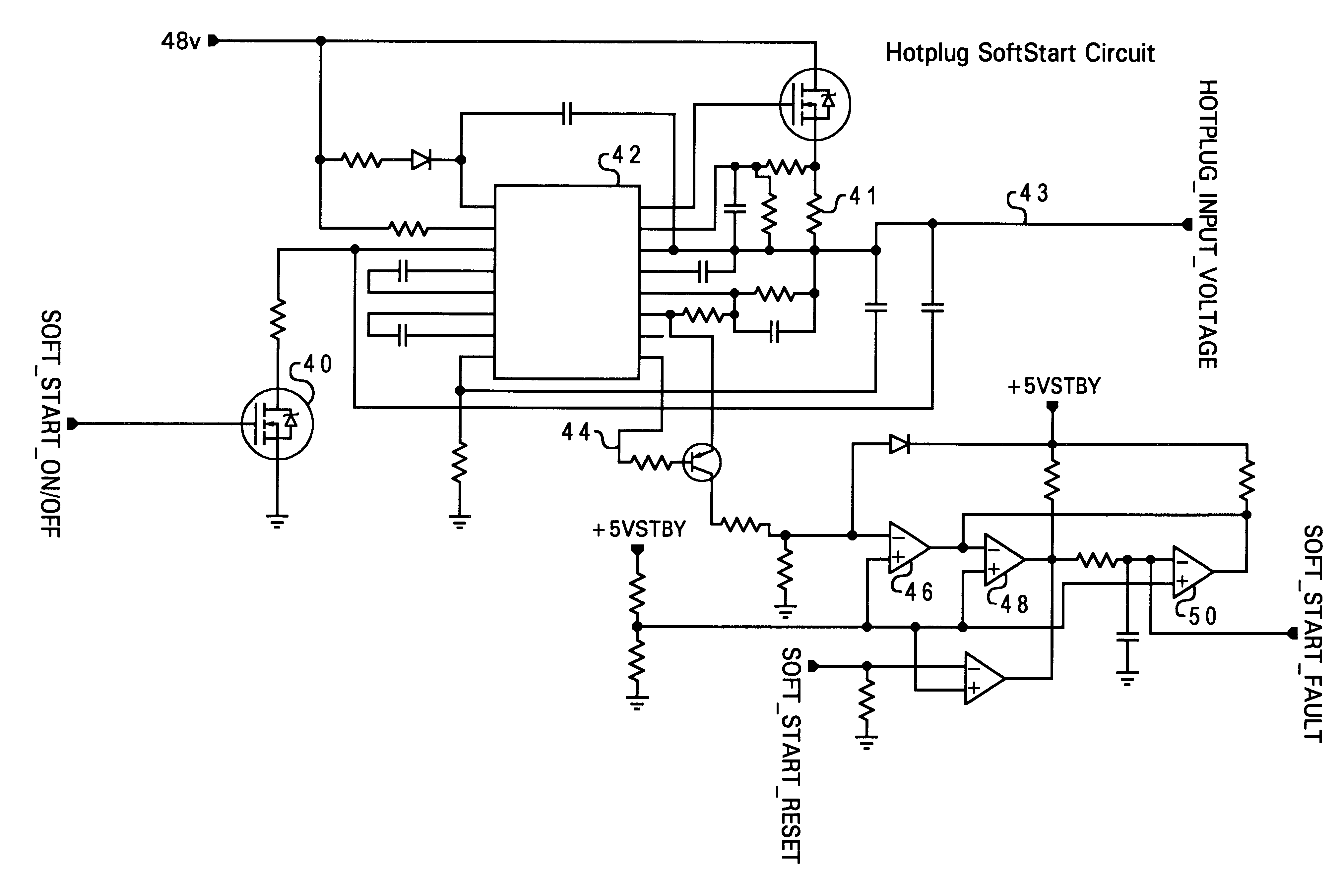
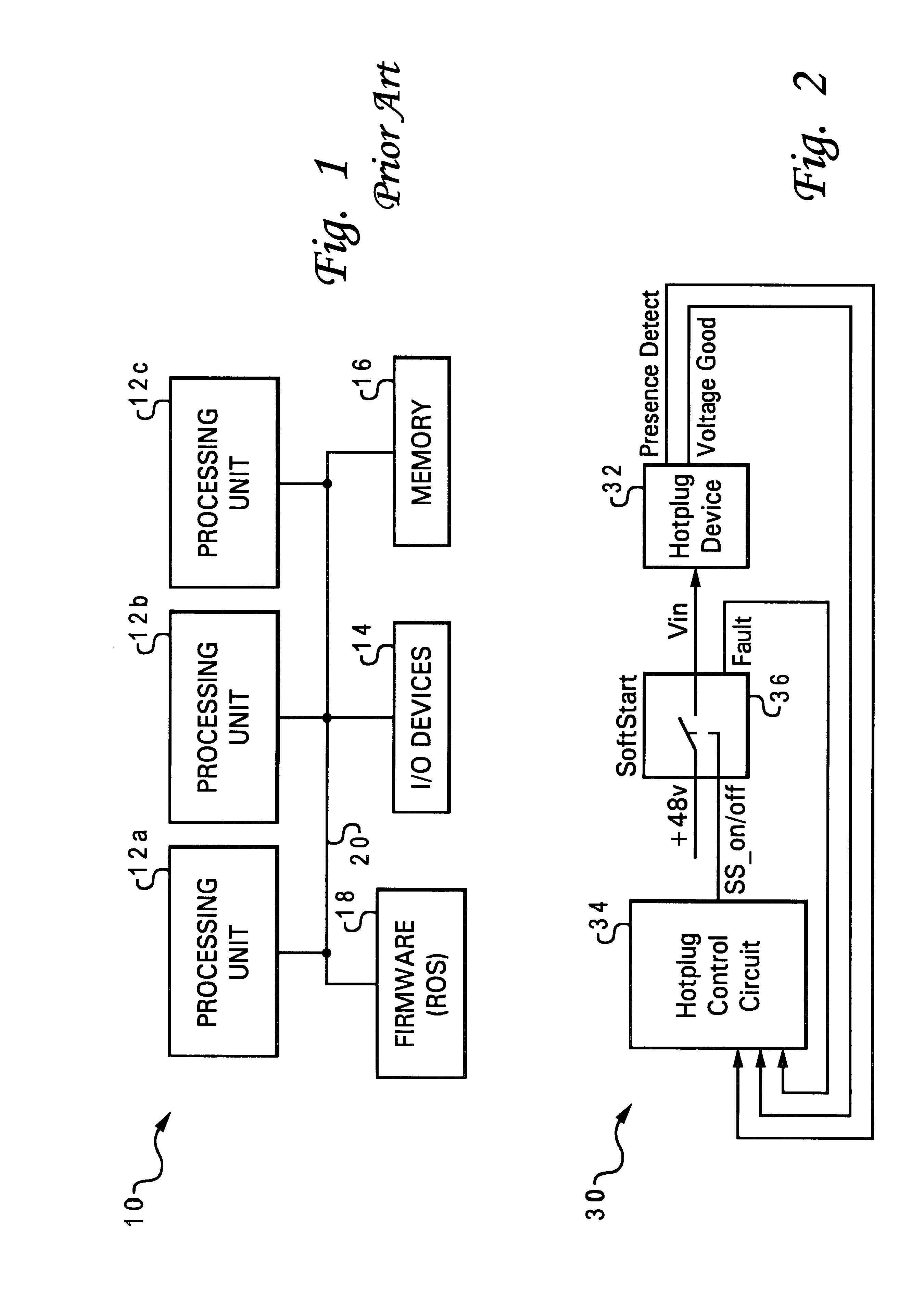
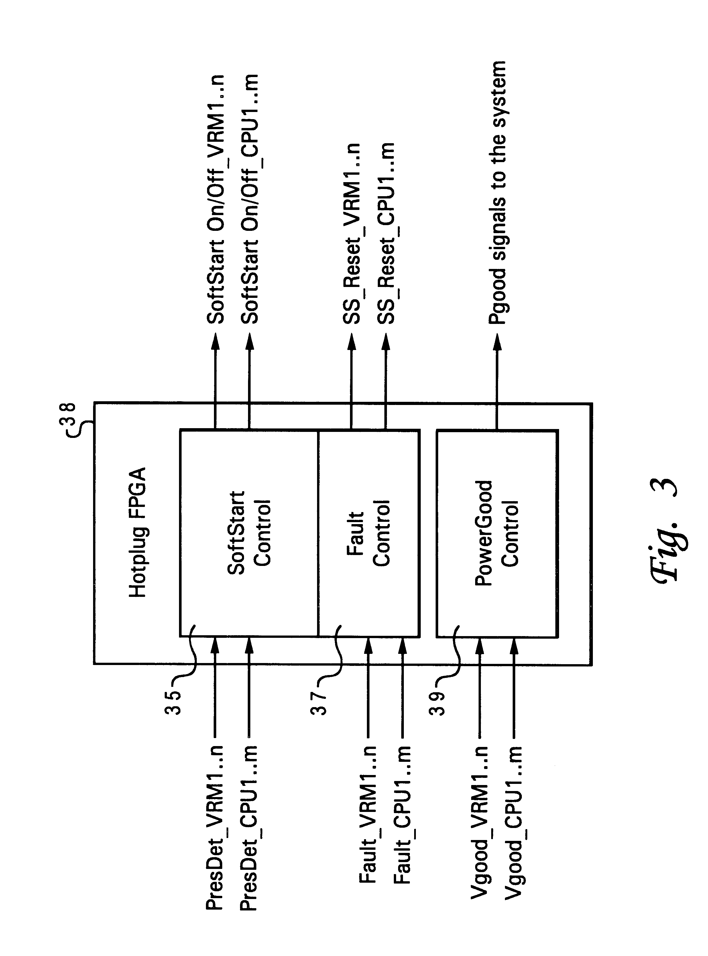
With reference now to the figures, and in particular with reference to FIG. 2, there is depicted one embodiment of a power subsystem 30 constructed in accordance with the present invention, for a computer system having a plurality of hot-pluggable devices. FIG. 2 depicts only one such hot-pluggable device 32, but it is understood that the following description applies to any number of hot-pluggable devices that may be provided by the overall computer architecture.

While the present invention may be applied to hot-plug peripheral devices, it is particularly adapted for use with non-peripheral components, such as the central processing units (CPUs or processors), or even lower-level components like a voltage regulator module (VRM). These components may be rendered hot-pluggable as described in U.S. Pat. applications Ser. Nos. 09 / 281,080 and 09 / 281,081, which are hereby incorporated. The CPUs and VRMs may be added or removed using connectors mounted on a system board.

In this embodiment,...


PUM


Abstract

A method of servicing a computer system without interrupting operation of the computer system, by connecting a computer component to a board of the computer system, detecting connection of the computer component to the system board using a control circuit, supplying power to the voltage input of the computer component in response to detecting the connection, and thereafter monitoring the power supplied to the voltage input of the computer component. The method may be used for core computer components such as CPU modules and voltage regulator modules. Power to the voltage input of the computer component is turned off in response to a determination that a current level of the power supplied to the voltage input exceeds a specified level. A fault signal is latched in an active state in response to the determination; the fault signal is reset when the component is removed from the system. The method also applies to a plurality of hot-pluggable components, wherein the power supplied to each component is individually monitored.

Description

1. Field of the InventionThe present invention generally relates to computer systems, particularly to a method of upgrading or servicing computer components, and more specifically to a method of controlling voltage sources to computer components that are removed or added during operation of the computer system, i.e., without powering down the computer system or otherwise interrupting service.2. Description of Related ArtModern computing systems are often constructed from a number of processing units and a main memory, connected by a generalized interconnect. The basic structure of a conventional multi-processor computer system 10 is shown in FIG. 1. Computer system 10 has several processing units (CPUs) 12a, 12b, and 12c which are connected to various peripheral, or input / output (I / O) devices 14 (such as a display monitor, keyboard, and permanent storage device), memory device 16 (random-access memory or RAM) that is used by the processing units to carry out program instructions, an...

Claims


Application Information

Patent Timeline
IPC IPC(8): G06F13/40G06F1/18G06F13/14G06F1/28G06F3/00
CPCG06F13/4081G06F1/28
Inventor JOHARI, GIRISH CHANDRAMUELLER, MARK WAYNETHOMSEN, PETER MATTHEWWALTER, LUCINDA MAE
Owner IBM CORP
Learn More