Infrared camera and infrared camera system having temperature selecting switch
a technology of infrared camera and temperature selection switch, which is applied in the field of infrared camera and infrared camera system, can solve the problems of reducing the dissipation power of imaging device 2, the inability of imaging device 2 to stabilize at a prescribed operating temperature, and the need for heating for a longer tim
- Summary
- Abstract
- Description
- Claims
- Application Information
AI Technical Summary
Benefits of technology
Problems solved by technology
Method used
Image
Examples
embodiment 1
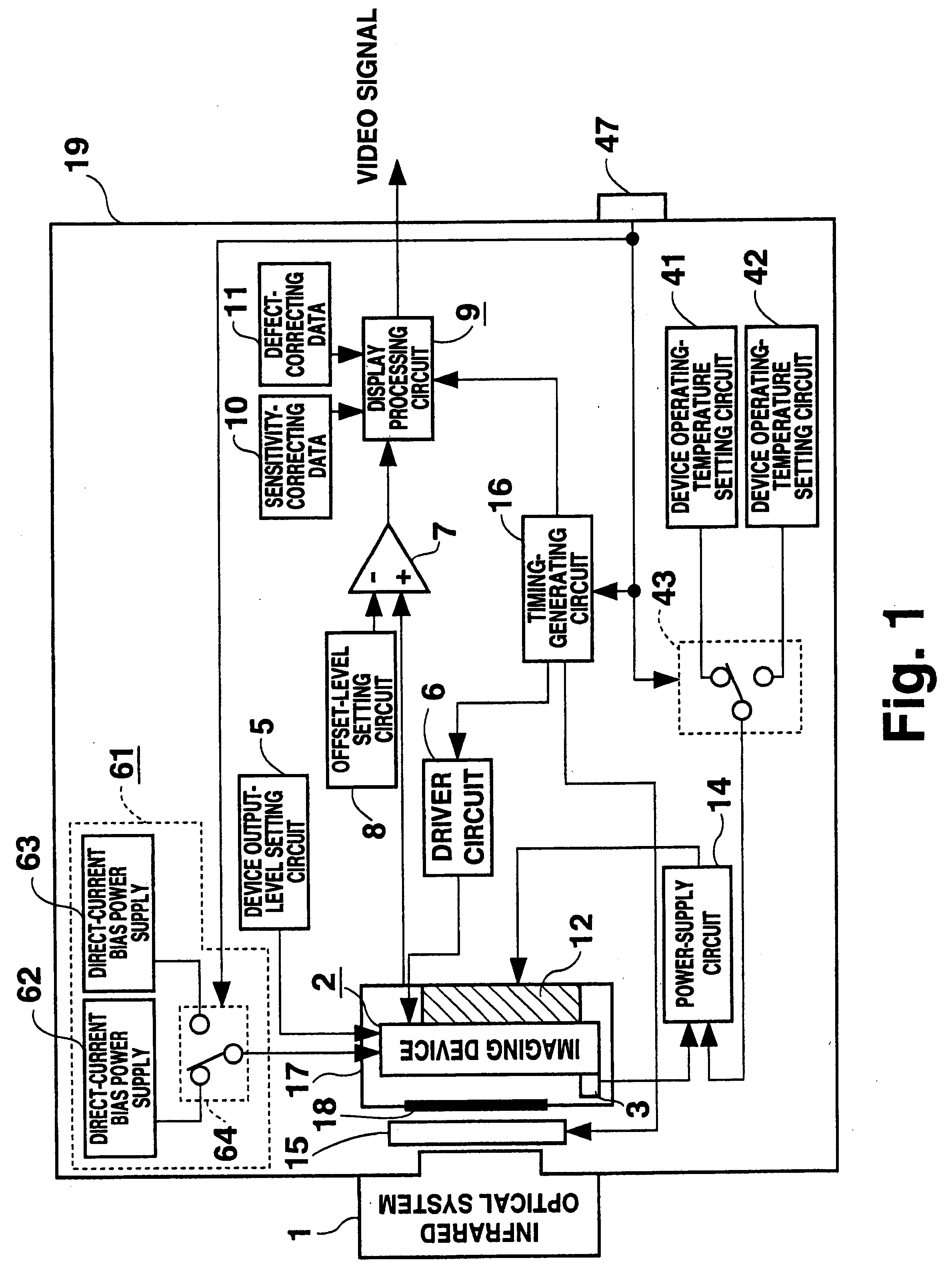
FIG. 1 is a block diagram showing Embodiment 1 of an infrared camera according to the present invention. In this figure, 1-3, 5-12, and 14-19 are the same as those in a conventional infrared camera. 41 is a device operating-temperature setting circuit; 42 is a device operating-temperature setting circuit for setting an operating temperature different from that set by the device operating-temperature setting circuit 41; 43 is a device operating-temperature change-over switch connected to the device operating-temperature setting circuits 41 and 42; 61 is a device output-level compensating circuit. The device output-level compensating circuit 61 includes a direct-current bias power supply 62, a direct-current bias power supply 63 for outputting a voltage different from that output by the direct-current bias power supply 62, and a direct-current bias power supply change-over switch 64 connected to the direct-current bias power supplies 62 and 63. 47 is an external switch fixed onto an e...
embodiment 2
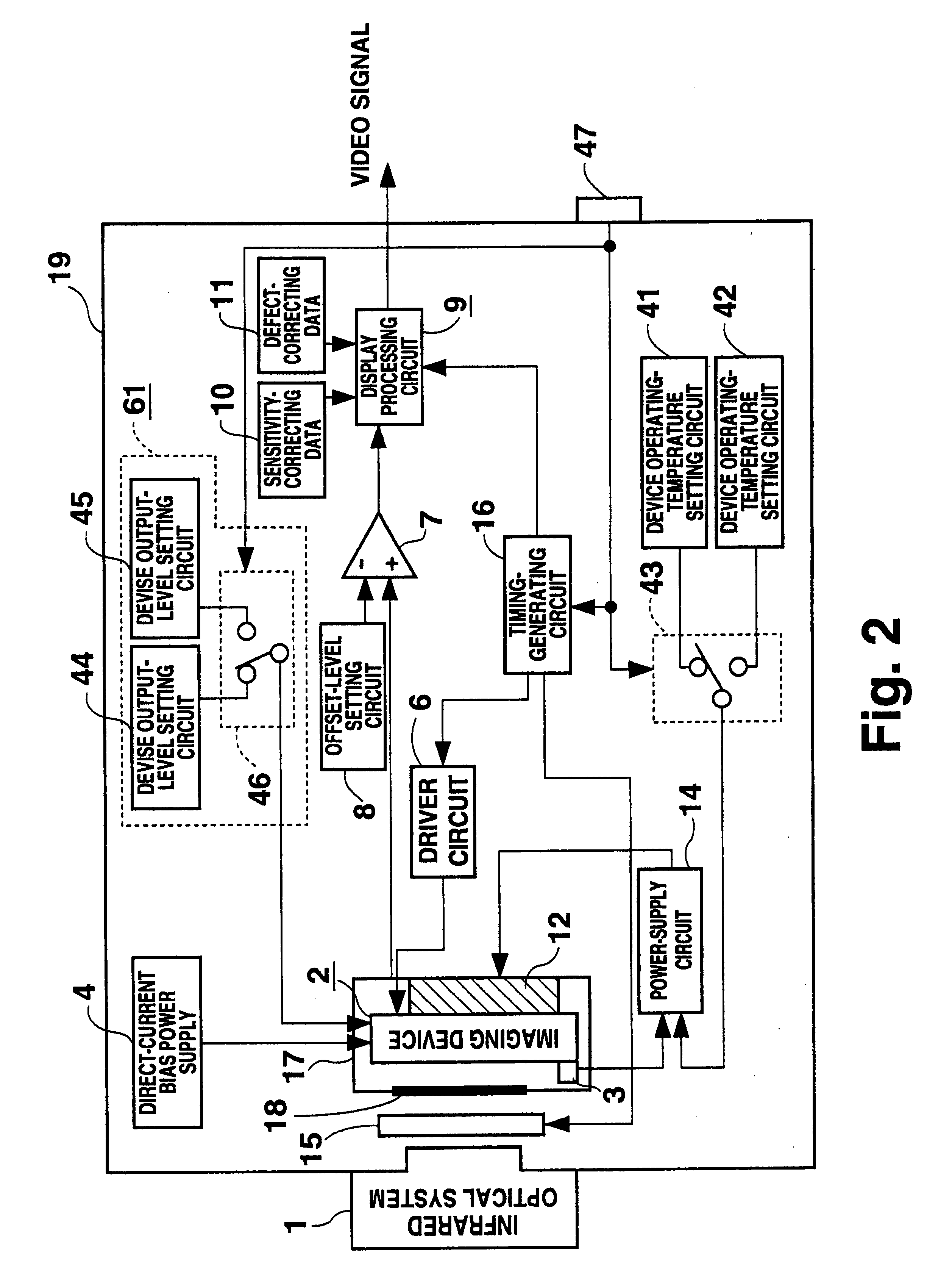
FIG. 2 is a block diagram showing Embodiment 2 of an infrared camera according to the present invention. In this Figure, 1-4, 6-12, and 14-19 are the same as those in a conventional infrared camera. 41, 42, 43, and 47 are the same as those in Embodiment 1. 61 is a device output-level compensating circuit, which includes a device output-level setting circuit 44, a device output-level setting circuit 45 for setting a value different from that set by the device output-level setting circuit 44, and a device output-level change-over switch 46 connected to the device output-level setting circuits 44 and 45.
Now, the operation of an infrared camera according to the present invention will be described. Before power application, the connection target of the device operating-temperature change-over switch 43 is selected, as with Embodiment 1, by the external switch 47 according to the environment temperature, that is to say, according to the ambient temperature for the enclosure 19. Imaging is...
embodiment 3
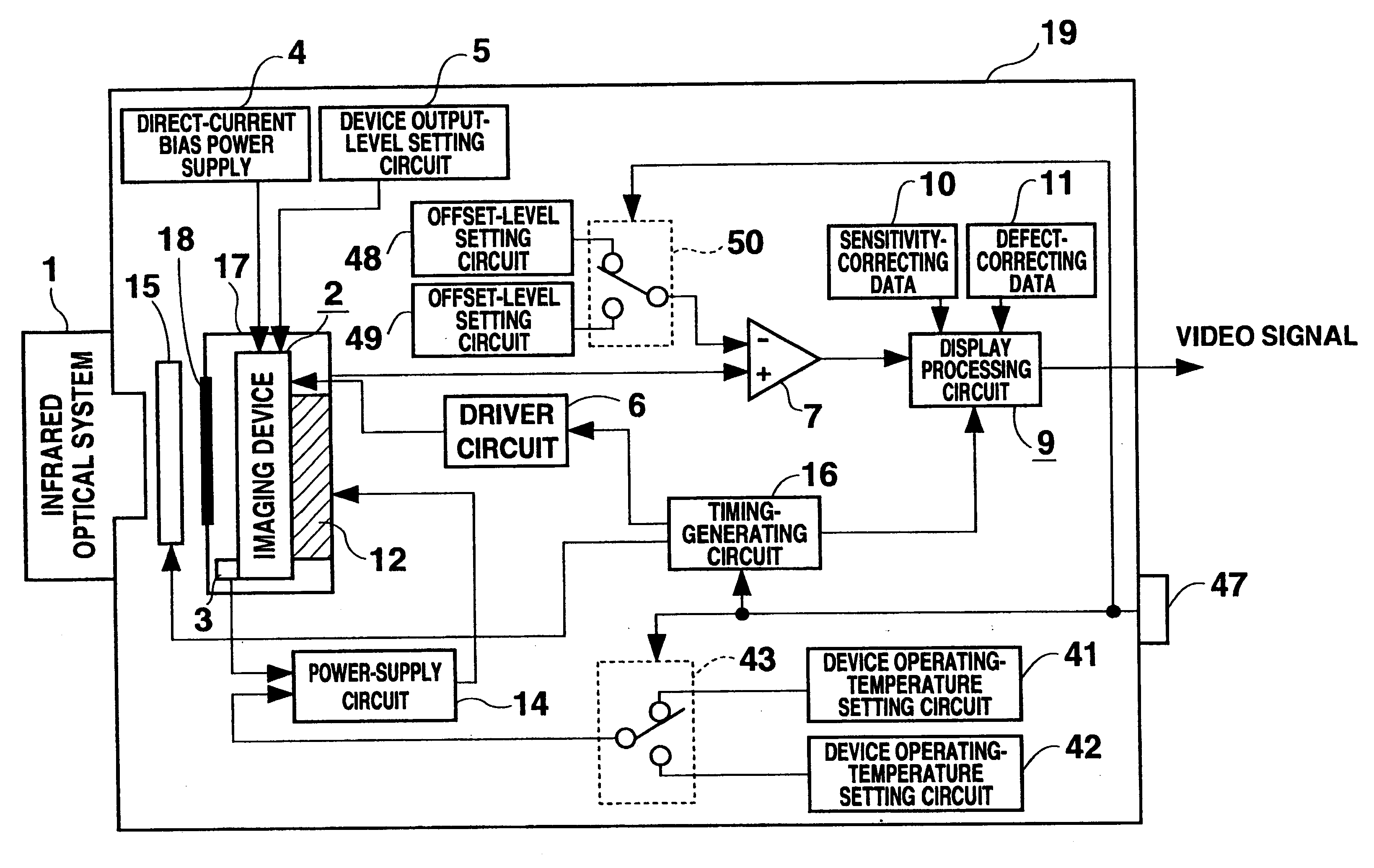
FIG. 3 is a block diagram showing Embodiment 3 of an infrared camera according to the present invention. In this figure, 1-7, 9-12, and 14-19 are the same as those in a conventional infrared camera. 41-43 and 47 are the same as those in Embodiment 1. 48 is an offset-level setting circuit; 49 is an offset-level setting circuit for outputting a value different from that output by the offset-level setting circuit 48; 50 is an offset-level change-over switch connected to the offset-level setting circuits 48 and 49.
Now, the operation of an infrared camera according to the resent invention will be described. Before power application, he connection target of the device operating-temperature change-over switch 43 is selected, as with Embodiment 1, by the external switch 47 according to the environment temperature, that is to say, according to the ambient temperature for the enclosure 19. Imaging is then performed. The resistance values of infrared-detecting devices 20-23 with a selected ope...
PUM
 Abstract
Description
Claims
Application Information
 - R&D
- Intellectual Property
- Life Sciences
- Materials
- Tech Scout
- Unparalleled Data Quality
- Higher Quality Content
- 60% Fewer Hallucinations
Browse by: Latest US Patents, China's latest patents, Technical Efficacy Thesaurus, Application Domain, Technology Topic, Popular Technical Reports.
© 2025 PatSnap. All rights reserved.Legal|Privacy policy|Modern Slavery Act Transparency Statement|Sitemap|About US| Contact US: help@patsnap.com


