Article identification apparatus and method

a technology of apparatus and objects, applied in the field of apparatus and methods for the identification of articles or objects, can solve the problems of inability to identify articles using automated systems, slow readout systems, and obvious presence of objects,

Inactive Publication Date: 2002-12-31
DEFENSE SEC OF THE STATE FOR THE +1
View PDF8 Cites 6 Cited by
  • Summary
  • Abstract
  • Description
  • Claims
  • Application Information

AI Technical Summary

Benefits of technology

It is an object of the present invention to provide a means for obtaining strong identification signals which are derived from physically robust features, created using materials which are acceptable for use on or in articles. In addition, the invention lends itself to high speed, automated checking. This is particularly advantageous when dealing with high volumes of articles.
Alternatively, the polarisation changing means may comprise at least one feature having an edge oriented at a non-zero angle, .theta., to a direction substantially parallel or substantially orthogonal to the first plane of polarisation. Preferably, the angle, .theta., is substantially 45.degree.. This provides the advantage that coupling of the microwave radiation having a first plane of polarisation to the waveguide connected to the detection means is maximised. For example, the one or more features may be a strip arranged on or within the article.
The apparatus may include both (i) means for determining the orientation of the means for changing the polarisation properties of the radiation and (ii) covert means for preventing the changing of the polarisation properties by the polarisation changing means. This has the advantage of providing a more complex identification code.

Problems solved by technology

Such features however, have the disadvantage that their presence is obviously apparent and this is not always desirable
Furthermore, whilst such features can be easily identified manually, such as labels or holograms, they are more difficult to identify using automated systems.
However, bar codes contain a lot of information, and whilst suitable for certain applications, for example supermarket product sales, such readout systems are too slow for applications requiring very high speed identification of articles.

Method used


Image

  • Article identification apparatus and method
  • Article identification apparatus and method
  • Article identification apparatus and method

Examples


Embodiment Construction

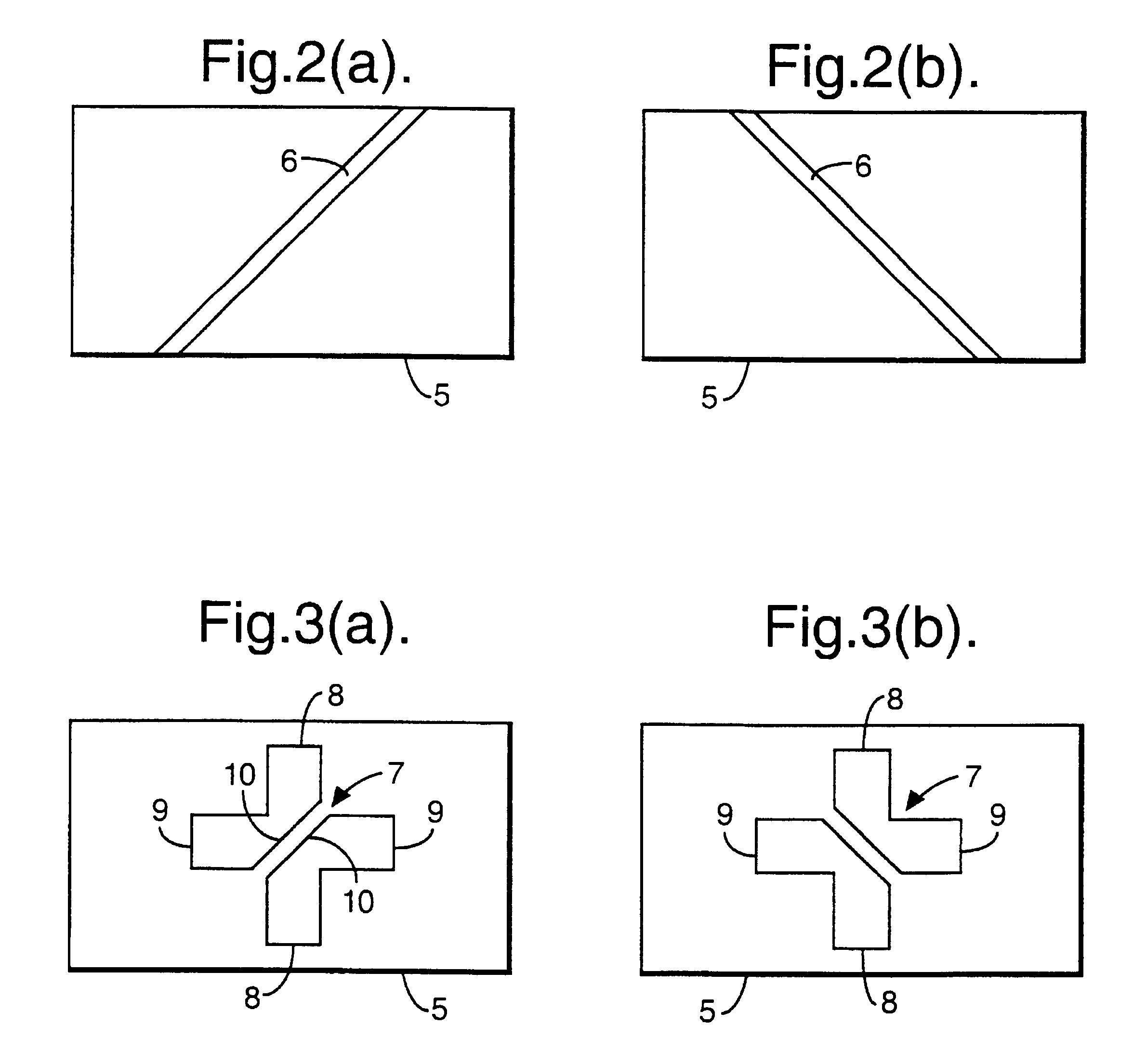
In these examples, the radiation used is substantially plane polarised and the change in polarisation properties caused by marked or tagged objects or articles comprises a change in the plane of polarisation. This, however, should not be seen as limiting as embodiments exploiting other types of non-randomly polarised radiation, such as circularly polarised radiation, may be used.

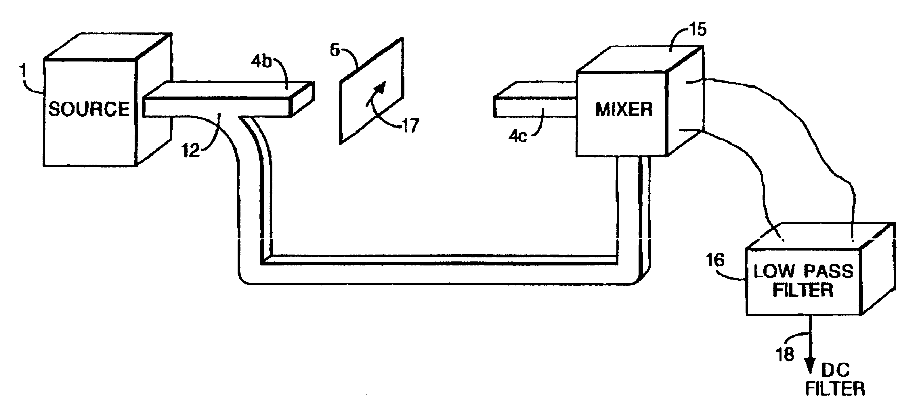
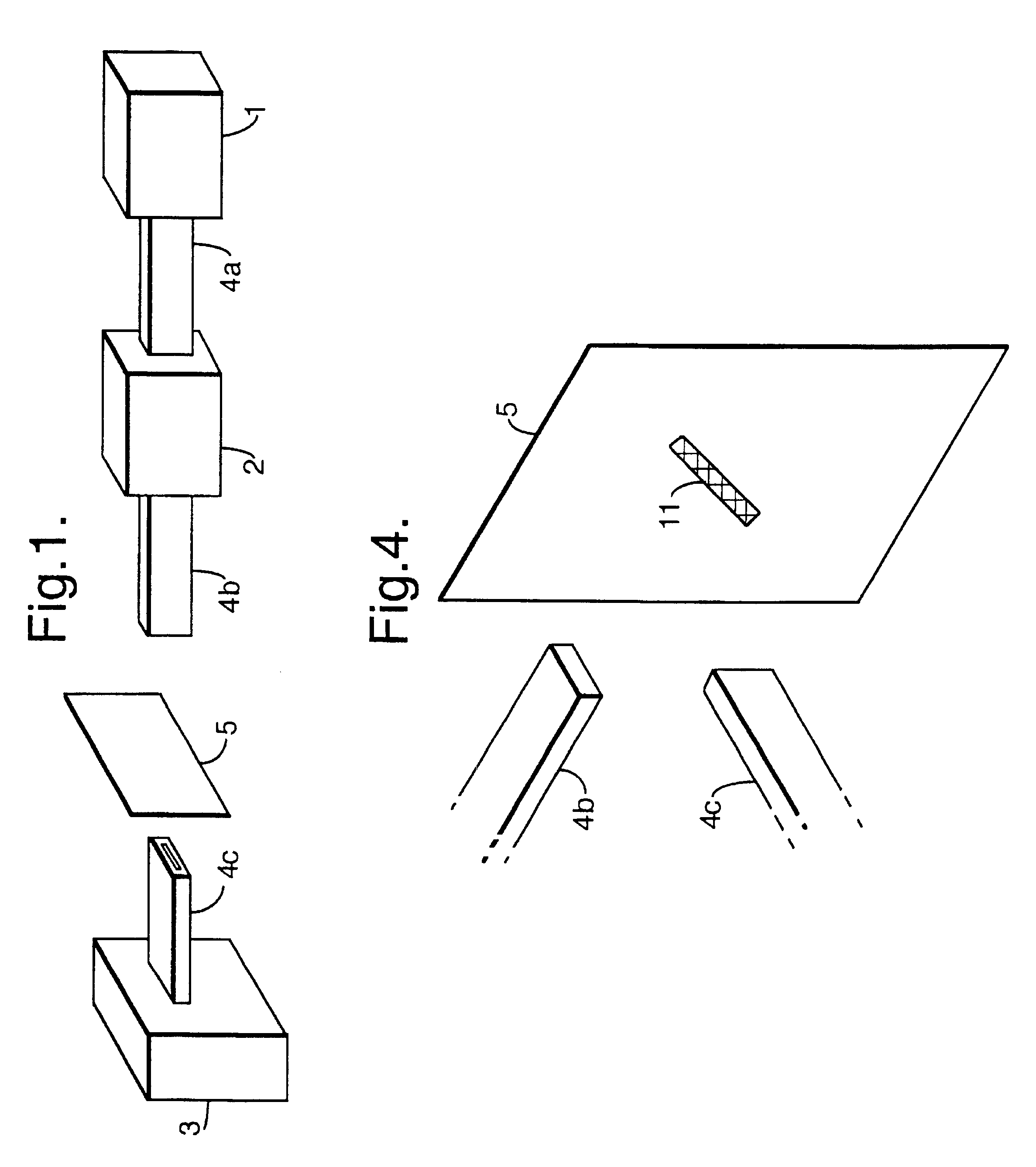
Referring to FIG. 1, a specific embodiment of the invention includes a microwave source 1 providing microwave radiation, an attenuator 2, a microwave detector 3 and various waveguides 4a, 4b, 4c. The source 1 may be any microwave source which may be coupled to a waveguide 4a. A suitable microwave detector 3 may be any microwave detector which may be coupled to a suitable waveguide.

During operation microwave radiation produced by source 1 passes via waveguide 4a to attenuator 2 which reduces the power to a safer level of about 1 mW. The attenuated radiation is directed, by waveguide antenna 4b, toward an obje...


PUM


Abstract

Apparatus for the identification of articles (5) endowed with device for changing the polarization properties of the radiation, comprising a source (1) of non-randomly polarized microwave radiation, and a detector (3) for detecting the change in polarization properties of the radiation. The microwave radiation may have a first plane of polarization and, in use, the device for changing the plane of polarization properties of radiation may change the first plane of polarization to a second plane of polarization. The detector (3) for detecting the change in polarization properties of radiation may comprise a receiving antenna (4c) connected to suitable microwave detector (3), where the receiving antenna (4c) is arranged to favour reception of radiation having the second plane of polarization. For example, the transmitting (4b) and receiving (4c) antennas may be waveguide antennas. The device for changing the polarization of radiation may comprise a feature having an edge oriented at a nonzero angle to a direction parallel with, or orthogonal to, the first plane of polarization. Typically, the feature may be a linear metallic strip, or may be a feature having a crossed dipole antenna structure. The apparatus may also comprise a device for determining the orientation of the feature or features. The polarization changing device may also comprise a covert structure for preventing the changing of the polarization properties by the polarization changing device in one or more selected location, wherein the arrangement of the one or more selected location provides an identification code.

Description

1. Field of the InventionThis invention is concerned with apparatus and a method for the identification of articles or objects.2. Discussion of Prior ArtConventionally, identification of articles has been achieved by the inclusion of features on the article which can be read by some means. These might include graphically complex features or holographic features. Such features however, have the disadvantage that their presence is obviously apparent and this is not always desirableFurthermore, whilst such features can be easily identified manually, such as labels or holograms, they are more difficult to identify using automated systems. Bar codes are a commonly used machine readable identification means. However, bar codes contain a lot of information, and whilst suitable for certain applications, for example supermarket product sales, such readout systems are too slow for applications requiring very high speed identification of articles.An object of the present invention is to provid...

Claims


Application Information

Patent Timeline
IPC IPC(8): G01S13/00G01S13/75G01S13/82G01S7/02G08B13/24H01Q15/00H01Q15/24H01Q1/22H01Q21/24B65G1/137G01S13/74G06K7/10G06K17/00G06K19/07
CPCG01S7/024G01S13/756G01S13/82G08B13/2417G08B13/2422G08B13/2442G08B13/2471H01Q1/22H01Q1/2216H01Q15/24H01Q15/242H01Q15/246H01Q21/245G06K19/067
Inventor BACKHOUSE, PAUL MBARRETT, CHRISTOPHER PBEALE, MARC I JGODFREY, ROBIN
Owner DEFENSE SEC OF THE STATE FOR THE
Why Eureka
Try Eureka