
Ventilation system for watercraft engine

a technology for watercraft engines and ventilation systems, which is applied in the direction of steam power plants, special-purpose vessels, vessel construction, etc., can solve the problems of increasing the weight of the engine, increasing the emissions of the engine, and producing large amounts of carbon monoxide and hydrocarbons

Inactive Publication Date: 2002-12-10
SANSHIN KOGYO CO LTD
View PDF14 Cites 18 Cited by
  • Summary
  • Abstract
  • Description
  • Claims
  • Application Information

AI Technical Summary

Benefits of technology

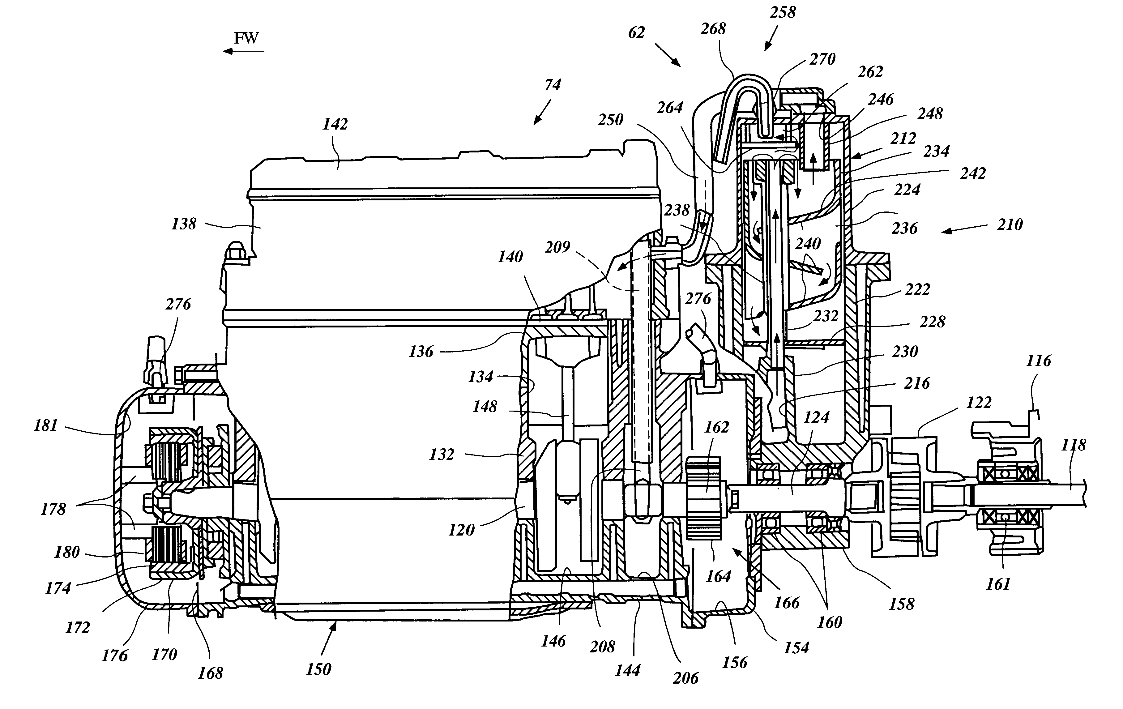
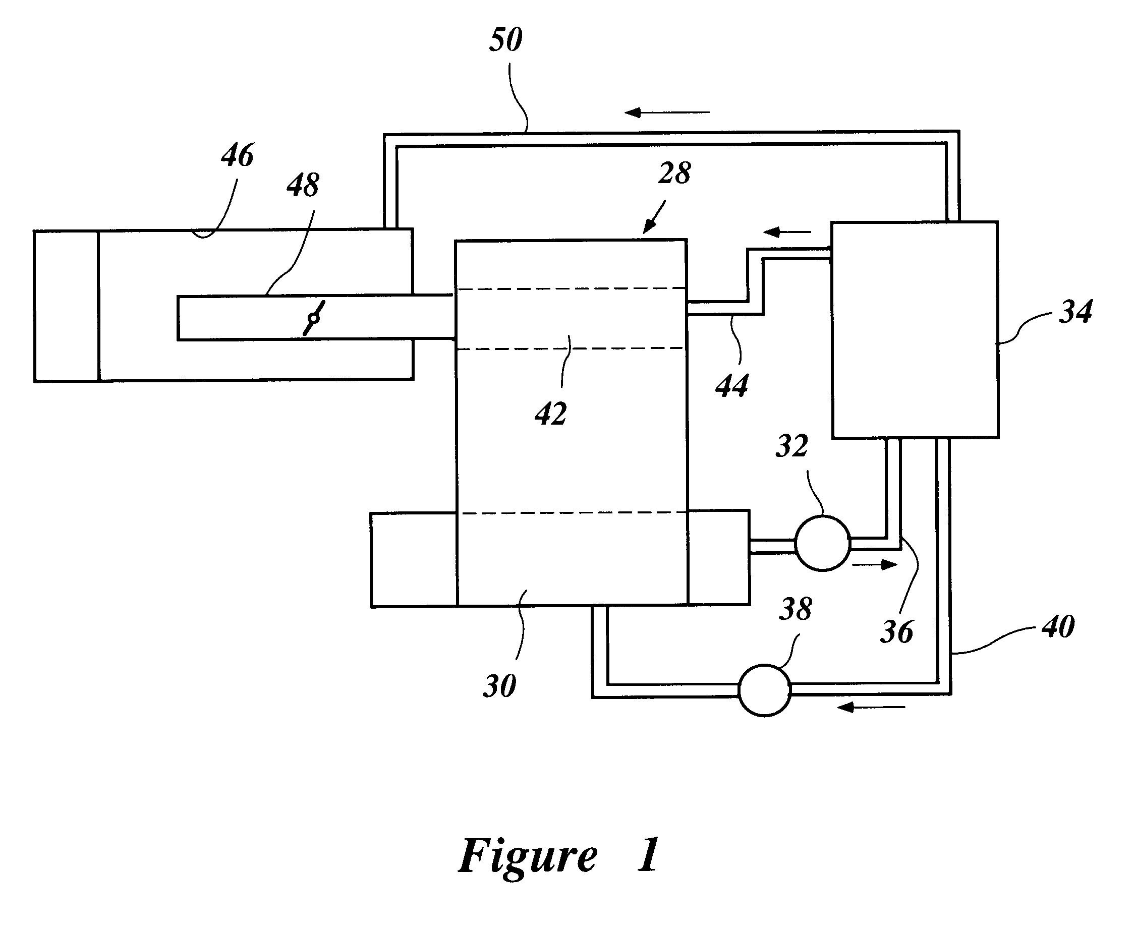
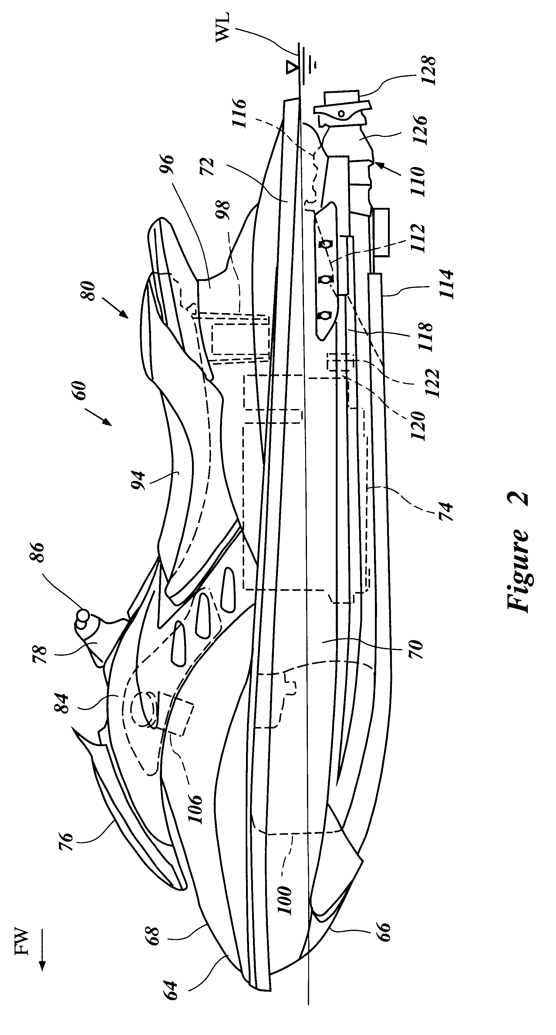
With primary reference to FIGS. 2-5, and additionally to FIG. 6, an overall construction of a watercraft 60 that employs a combined lubrication and ventilation system 62 arranged in accordance with certain features, aspects and advantages of the present invention will be described. The combined lubrication and ventilation system 62 has particular utility in the context of a personal watercraft and thus is described in the context of a personal watercraft. The combined system, however, can be applied to other types of recreational vehicles as well, such as, for example, small jet boats, all-terrain vehicles and the like.

Problems solved by technology

One disadvantage of two-cycle engines, however, is that they produce relatively high emissions.
In particular, large amounts of carbon monoxide and hydrocarbons are produced during operation of the engine.
When steps are taken to reduce these emissions, other undesirable consequences typically result, such as an increase in weight of the engine, the cost of manufacture, and / or the reduction of power.
However, adapting four-cycle engines for use in personal watercraft has its own engineering and technical challenges due to, at least in part, the limited space available within the hull of a personal watercraft.
Additionally, such a flow of oil into the induction system can interfere with normal operation of the engine.

Method used


Image

  • Ventilation system for watercraft engine
  • Ventilation system for watercraft engine
  • Ventilation system for watercraft engine

Examples


first embodiment

With reference to FIGS. 5 and 6, the combined lubrication and ventilation system 62 will now be described below.

The engine 74 preferably employs a lubrication system that delivers lubricant oil to engine portions that need lubrication for inhibiting frictional wear of such portions. A closed-loop type, dry-sump lubrication system 210 preferably is applied in this embodiment. The lubrication system 210 comprises a lubricant oil tank assembly or oil container 212, a feed passage 214, a scavenge passage 216, a feed pump 218 and a scavenge pump 220.

The oil tank assembly 212 stores lubricant oil for lubricating the engine 74. The oil tank assembly 212 comprises a lower tank body 222 unitarily formed with the intermediate shaft and pump housing 158 and is located thereabove in a rear area of the engine body 150. An upper tank body 224 is affixed to an upper portion of the lower tank body 222. The feed passage 214 couples the oil tank assembly 212 with internal delivery passages or "oil ga...

third embodiment

FIG. 12 illustrates yet another modification of the combined lubrication and ventilation system 62 illustrated in FIG. 6. In this arrangement, the ventilation passage 268 extends from the cylinder head cover member 142 where the ventilation chamber 262 is located similarly to the arrangement shown in FIG. 9. The same check valve 300 used for the third embodiment and is shown in FIG. 11 also is applied for this embodiment and is disposed within the ventilation passage 268.

FIG. 13 illustrates yet another modification of the combined lubrication and ventilation system 62 illustrated in FIG. 6. In this arrangement, a first ventilation chamber 262a is disposed atop of the oil tank assembly 212, while a second ventilation chamber 262b is disposed separately either from the oil tank assembly 212 or the cylinder head cover member 142. Both the first and second ventilation chambers 262a, 262b form labyrinth paths therein. The ventilation passage 268 comprises an upstream portion 268a that co...


PUM


Abstract

A ventilation system for a watercraft engine includes an improved construction that can inhibit oil in an oil container from flowing into an air induction system even if the watercraft capsizes. The engine includes an engine body and an air induction system that introduces air to combustion chambers. A lubrication system is arranged to lubricate at least a portion of the engine body with lubricant oil. The lubrication system includes an oil tank assembly out of the engine body. A ventilation system is arranged to separate a gaseous component from a liquid component. The ventilation system includes a separator configured to separate the gaseous component from the liquid component. A ventilation passage connects the separator with the air induction system. A return passage couples a bottom portion of the ventilation passage with inside of the engine body.

Description

PRIORITY INFORMATIONThis application is based on and claims priority to Japanese Patent Applications No. 2000-284753, filed Sep. 20, 2000, No. 2001-108382, filed Apr. 6, 2001 and No. 2001-276355, filed Sep. 12, 2001, the entire contents of which are hereby expressly incorporated by reference.1. Field of the InventionThe present invention relates generally to an ventilation system for a watercraft engine, and more particularly to an improved induction system which includes a vapor return system.2. Description of Related ArtPersonal watercraft have become very popular in recent years. This type of watercraft is quite sporting in nature and carries one or more riders. A relatively small hull of the personal watercraft defines a rider's area above an engine compartment. An internal combustion engine powers a jet propulsion unit which propels the watercraft. The engine lies within the engine compartment in front of a tunnel formed on the underside of the hull. A jet propulsion unit, whic...

Claims


Application Information

Patent Timeline
Patent Type & Authority Patents(United States)
IPC IPC(8): B63J2/00B63B35/73B63J2/06B63H11/08F01M11/00F01M11/02F01M13/00F01M13/04
CPCB63B35/731B63J2/06Y02T70/72B63B34/10Y02T70/00
Inventor MURAMATSU, HITOSHISUGANUMA, NOBORU
Owner SANSHIN KOGYO CO LTD
Learn More