Eureka AIR delivers breakthrough ideas for toughest innovation challenges, trusted by R&D personnel around the world.

Shearing lifting jack

a lifting jack and jack technology, applied in the field of sheep shearing jacks, can solve the problems of minor nicks and grazes, requires strength and stamina, etc., and achieve the effects of easy dragging a sheep, high engineering tolerance, and fast and easy shearing

Inactive Publication Date: 2002-11-12
KORJENIC HAMID
View PDF6 Cites 16 Cited by
  • Summary
  • Abstract
  • Description
  • Claims
  • Application Information

AI Technical Summary

Benefits of technology

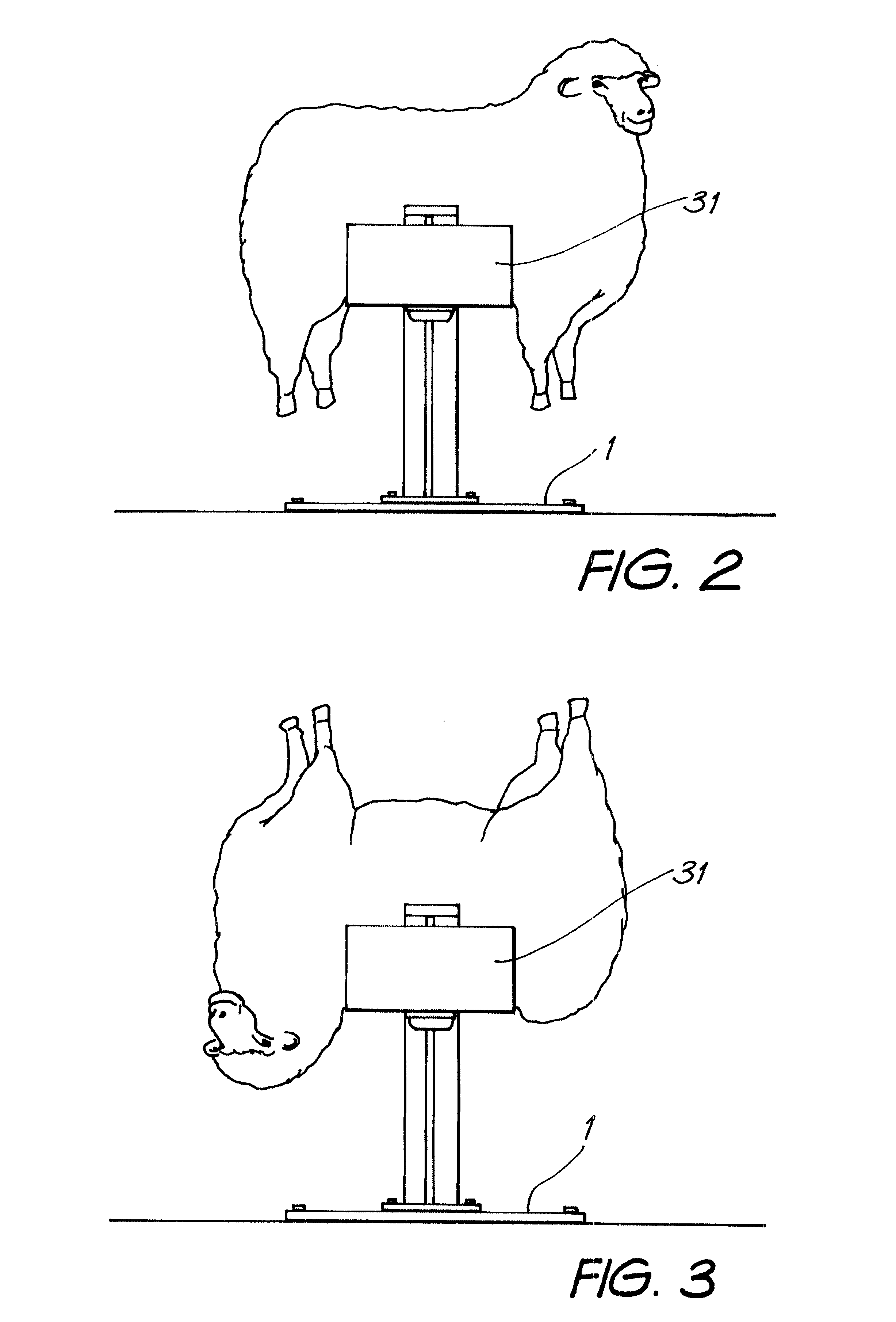
According to the present invention there is provided a lifting jack for shearing sheep, which comprises a cradle for holding a sheep on its back or stomach and which is shaped so as to allow the sheep to be rolled from its back to its stomach or vice versa during the shearing operation, lifting means in the form of a chain and sprocket mechanism to move the cradle from a first loading / unloading position adjacent the floor of a shearing shed or other suitable location for shearing sheep and a second raised position for shearing the sheep approximating the height of a work bench so that the sheep is able to be lifted whilst it is shorn in order that the shearer avoids bending over the sheep, the lifting means being operable by a suitably located foot pedal between the first loading / unloading position and second shearing position by a single unassisted shearer, so that in use a shearer is able to place a sheep in the cradle at floor height and whilst either holding the sheep himself or otherwise restraining the sheep with a chain or belt or the like is then able to cause the cradle to be lifted, and wherein locking means are provided in association with the foot pedal so that after a predetermined length of travel corresponding to the required raising of the cradle, the pedal can be locked in its lower position, without the need for the shearer to keep his foot thereon, thereby preventing the cradle from returning to its first loading / unloading position until shearing has been completed when the locking mechanism is released to allow the cradle to be returned.
For example a simple chain drawn over a single sprocket, where the chain is affixed at or near one end to the cradle and the where other end is attached to s foot or hand operable pedal, will allow the shearer to push down on the raised pedal, when the sheep is loaded to the cradle, thereby causing the cradle to lift as the pedal is pushed down. Preferably the weight of the cradle and sheep will be offset to a reasonable degree by the weight of the foot pedal (ie they will be in rough equilibrium with the greater weight provided by the cradle and sheep) so that the effort required to raise or lower the sheep is lessened.
In this embodiment, a second sprocket is suitably positioned in relation to the second chain so that a motor either directly or indirectly operates on the second sprocket to cause the whole chain assembly (comprising both chain portions) and hence the cradle to move. In this embodiment, the motor itself, may act as a brake to prevent return of the cradle to the first loading position. It will also be appreciated that the foot pedal itself may in fact be removed altogether as it is effectively redundant. However, with advantage, it may be useful to incorporate it in the design of such a jack to facilitate operation thereof when power is not available, or at least readily available, in the field. In addition the foot pedal may provide added safety by allowing manual locking of the jack in addition to the braking afforded by the motor.
A shearing lifting jack, according to one embodiment of the invention, is preferably of metal design, constructed primarily from mild steel and employing high engineering tolerances in its construction. The shearing lifting jack is preferably made from steel plate of sufficient quality to ensure that it remains robust. The shearing lifting jack of this embodiment is relatively heavy being around 83 kg, although its weight will depend on the particular gauges etc of the materials specified. This weight helps the shearing lifting jack remain in a stable position during use. The overall height of the shearing lifting jack is preferably around 1030 mm. It needs no more that one square meter of floor space. Thus a shearer needs only 1 sq m of space in the shearing shed when operating the shearing lifting jack, allowing for both the shearer himself and the sheep as well as the jack, although in practice it is preferable to allow say a space of 1.5 sq m per jack. One jack is utilised per shearer With advantage, the shearing lifting jack is affixed to the floor with screws for a wooden floor or with bolts for a concrete floor. It must be remembered that the sheerer is dealing with untrained animals in the form of sheep of varying size and weight from 15 to 140 kg. However, working with this lifting jack makes it very easy for the shearer.

Problems solved by technology

This means that the shearer is bending over the sheep whilst shearing it, which requires strength and stamina on the part of the shearer to restrain the sheep whilst he shears it.
As the sheep struggles it is likely that at least minor nicks and grazes will result.

Method used


Image

  • Shearing lifting jack
  • Shearing lifting jack
  • Shearing lifting jack

Examples


Embodiment Construction

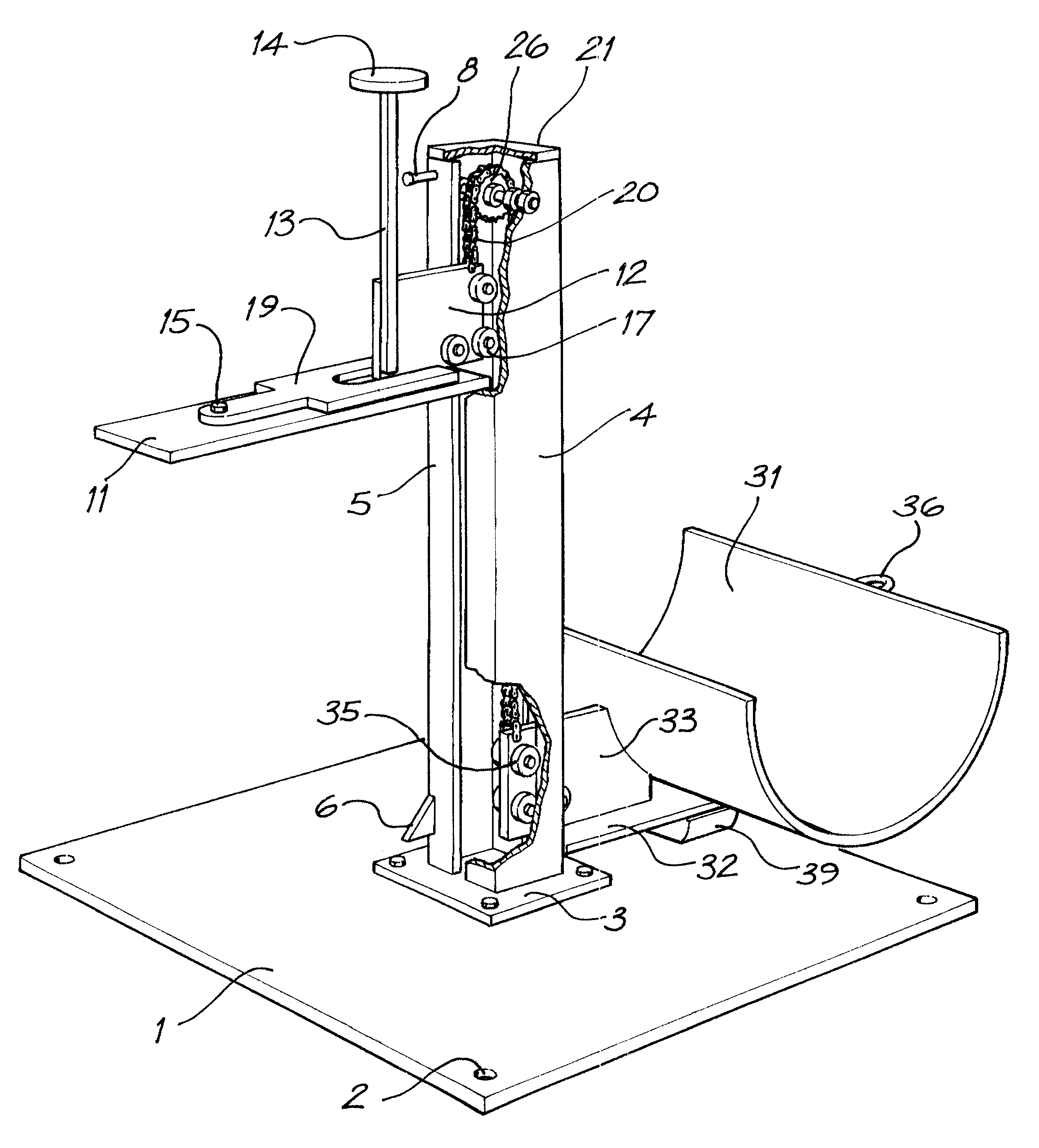
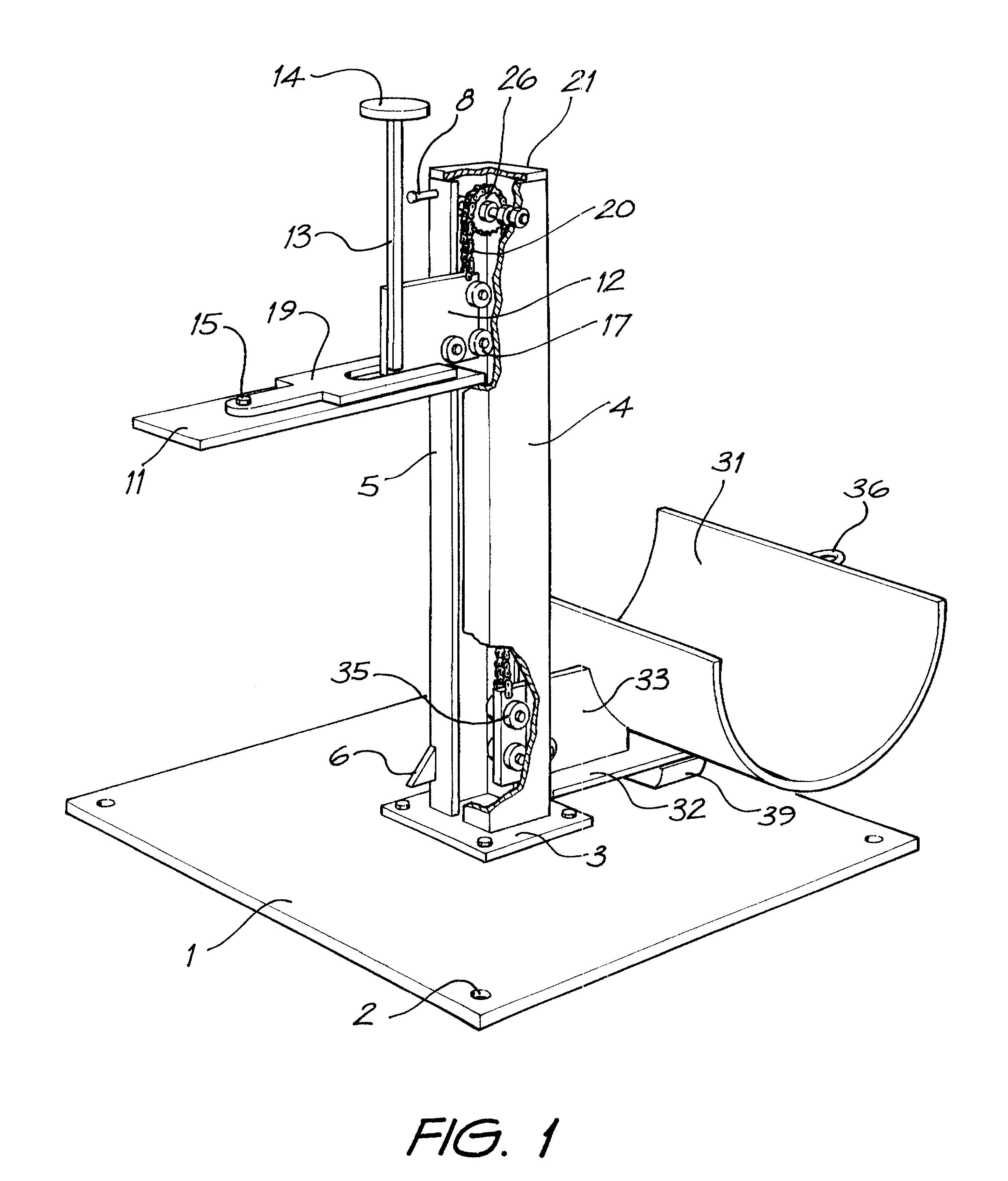
Referring generally to the Figures and especially FIG. 1, there is shown a shearing lifting jack according to a first embodiment of the invention. A base plate 1 is preferably made from 5 to 8 mm mild steel plate and has an area of 1 sq m. The base plate 1 is designed to support the total structure of the shearing lifting jack. The base plate 1 has an outer set of four holes 2 in each corner. Screws or bolts (not illustrated) are used to affix the base plate 1 to the floor or ground as required utilising this outer set of holes 2.

The base plate 1 also has four additional holes located approximately 150 mm apart near the centre by means of which there is attached to the base plate 1, by means of suitable nuts and bolts or other fasteners, a support plate 3 also with 4 holes in each corner corresponding to the centrally located holes in base plate 1.

Welded to the support plate 3 are two C-shaped steel sections, being a right half post 4 and left half post 5 which in combination form a...


PUM


Abstract

Shearing lifting jack for shearing sheep comprises a cradle (31) for holding a sheep on its back or stomach and which is shaped so as to allow the sheep to be rolled from its back to its stomach or vice versa during the shearing operation. Lifting means for example in the form of a rolling chain (20) is provided to move the cradle from a first loading / unloading position adjacent the floor of a shearing shed or other suitable location for shearing sheep and a second raised position for shearing the sheep approximating the height of a work bench. This allows the sheep to be lifted whilst it is shorn in order that the sheerer avoids bending over the sheep. The lifting means is operable between the first loading / unloading position and second shearing position by a single unassisted shearer.

Description

This invention relates to improvements in the sheep shearing industry and in particular relates to means for mechanically lifting a sheep from the floor and means for holding the sheep in that position for a shearer to shear it.Sheep are generally shorn by a shearer who, whilst holding the sheep on the floor, straddles the sheep and removes the fleece according to common practice with a pair of hand-held shears. This means that the shearer is bending over the sheep whilst shearing it, which requires strength and stamina on the part of the shearer to restrain the sheep whilst he shears it. Furthermore, he must at all times keep one hand on the sheep whilst wielding the cutting shears with the other. As the sheep struggles it is likely that at least minor nicks and grazes will result.OBJECT OF THE INVENTIONIt would therefore be highly desirable to provide a lifting arrangement suitable for holding a sheep which is to be shorn and raising it to the equivalent of bench height or thereab...

Claims


Application Information

Patent Timeline
IPC IPC(8): A01K1/06A01K1/00A01K14/00A01K15/00
CPCA01K1/0613A01K14/00A01K15/00
Inventor KORJENIC, HAMID
Owner KORJENIC HAMID
Why Eureka
Eureka Blog
Learn More