
Current distribution device

a current distribution and distribution device technology, applied in the direction of riveted connection, coupling device connection, transportation and packaging, etc., can solve the problems of inability to distribute current and complex assembly

Inactive Publication Date: 2002-11-05
AUDIO OHM DI TONANI CATERINA E C +1
View PDF20 Cites 43 Cited by
  • Summary
  • Abstract
  • Description
  • Claims
  • Application Information

AI Technical Summary

Benefits of technology

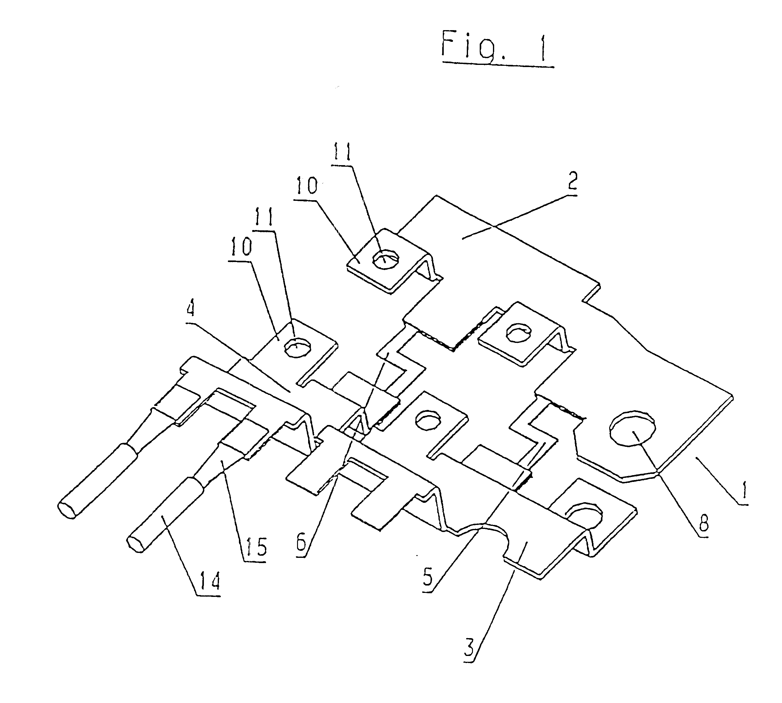
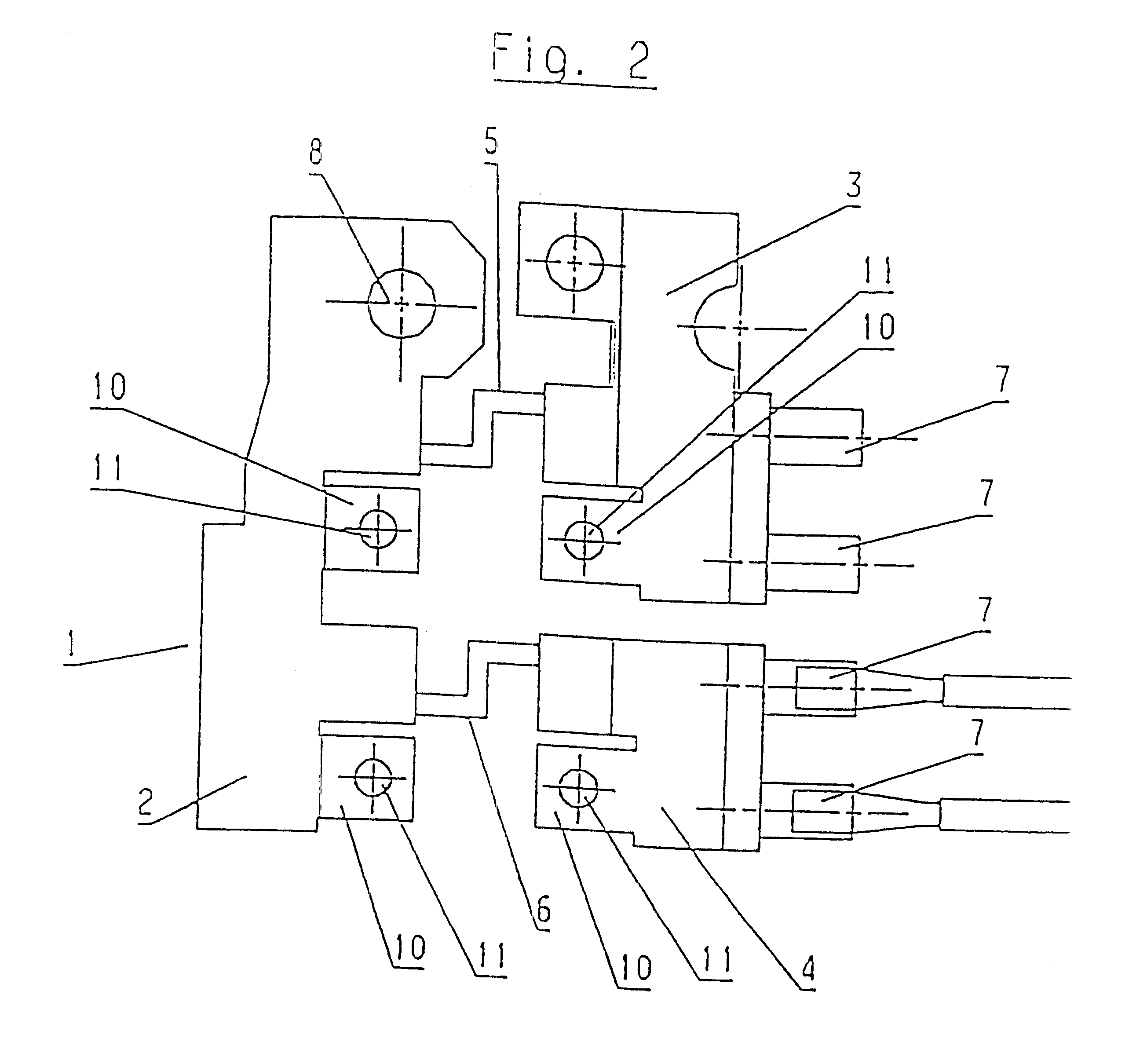
In accordance with the invention, the inseparable connections of the bridge-like fuse areas to the first area and the respectively associated second area make any additional individual parts such as screws etc. superfluous and as a result the production of the current distribution device is correspondingly simplified. The fuse areas can be advantageously integrated into the current distribution device as a result of the fact that according to the invention, bridge-like fuse areas are provided instead of conventional fuse modules. This means that compact and weight-saving current distribution devices can be obtained.
In the aforementioned production processes, it may be an advantage, when there is a plurality of second areas, for these second areas to remain connected together until the end by means of webs which are removed only after all the machining steps have been performed. This makes it possible to machine the current distribution device blanks in a more effective and stable manner.

Problems solved by technology

This solution does, however, suffer from the drawback that a large number of individual parts such as screws, nuts, washers etc. is necessary and that assembly is very complex.
The subject matter known therefrom relates to a fuse; current distribution is not possible by means thereof and is not envisaged either.

Method used


Image

  • Current distribution device
  • Current distribution device
  • Current distribution device

Examples


Embodiment Construction

The invention is based upon the technical problem of providing a simple-to-manufacture current distribution device, particularly for motor vehicles, and providing a method of producing such a current distribution device.

In accordance with the invention, this technical problem is solved by a current distribution device comprising the features of claim 1 or a current distribution device comprising the features of claim 6. The technical problem upon which the invention is based is also solved by a production method comprising the features of claim 13 or 14.

A current distribution device according to a first fundamental embodiment of the inventive concept comprises a first area made of electrically conductive material and having at least one electrical connection. Depending on where the current distribution device is placed within a power supply network, the following can e.g. be connected to the connection: current leads, a line to the positive pole of a battery, or a ground lead. If th...


PUM


Abstract

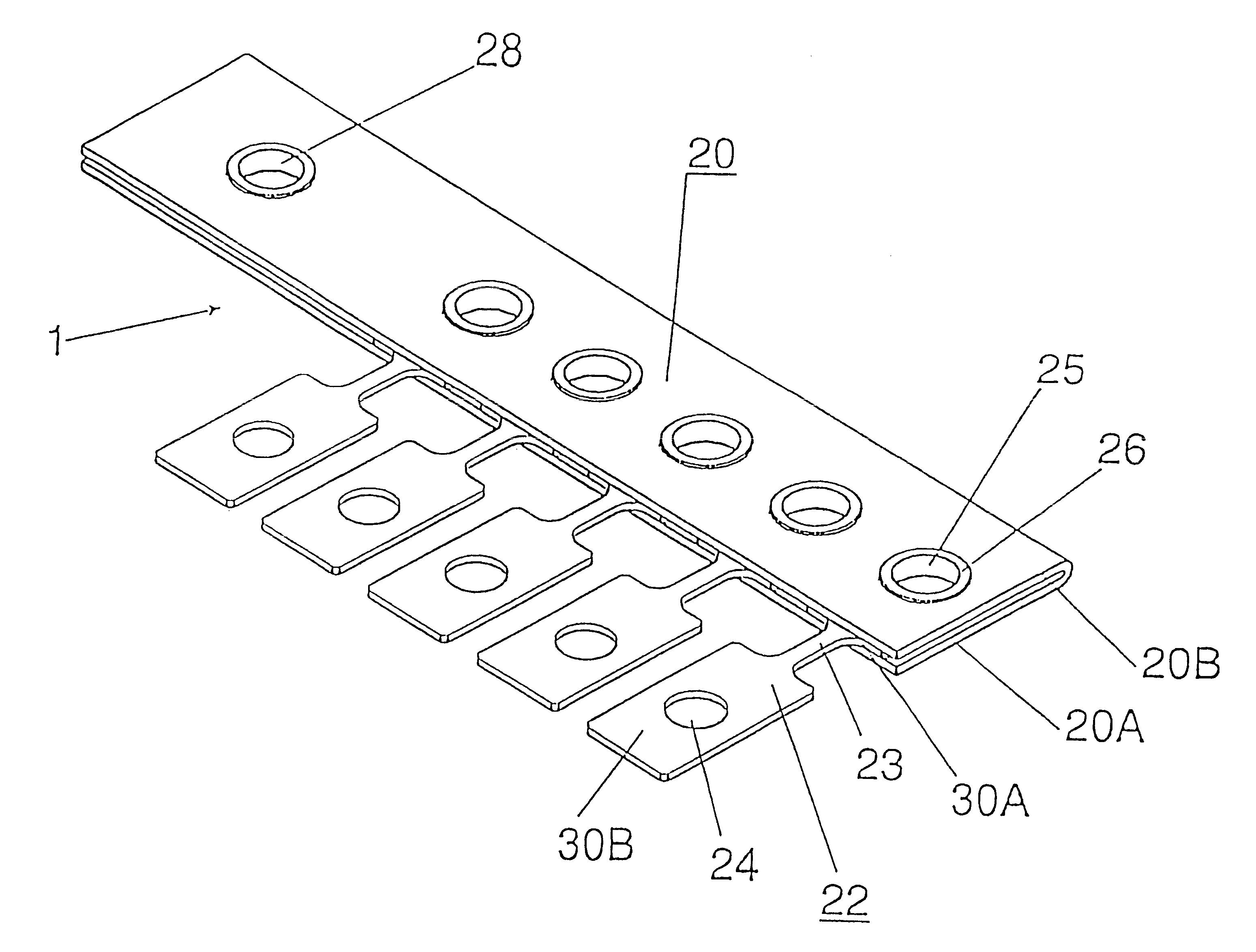
A voltage distribution device for use especially in motor vehicles, includes a first area (2) made of conductive material and fitted with at least one electrical connection (8), at least two separate second areas (3, 4) made of conductive material and fitted with at least one electrical connection each (7), and bridge-like fuse areas (5, 6) made of conductive material, which each link the second areas (3, 4) with the first (2) and are inseparably connected to the first and associated second area. The bridge-like fuse areas (5, 6) each have a cross-section of material calibrated along a longitudinal section according to material thickness and / or depth. In another embodiment of the invention, in a voltage distribution device for use especially in motor vehicles, a first area (2) made of conductive material and with at least one electrical connection (8), and at least two second areas (3B) made of conductive material and with at least one electrical connection each (4), are linked by bridge-like fuse areas made of conductive material (3), whereby these fuses (3) are inseparably connected to the first area (2) by deep-draw sleeves (5).

Description

The invention relates to a current distribution device, particularly for motor vehicles.Current distribution devices are used to distribute or branch electrical currents within a power supply network. To ensure that the current distribution is protected, it is advantageous to provide the current distribution device with fuses.PRIOR ARTFor this purpose, use has so far been made of fuse modules which are available in various standard fuse values and are screwed on to a current distribution component. This solution does, however, suffer from the drawback that a large number of individual parts such as screws, nuts, washers etc. is necessary and that assembly is very complex.A cable fuse is known from WO 89 / 03117. This known fuse for cables comprises, in addition to an insulating housing, an integral metal element which connects together, via a fuse area, metal-coated plug-in connections for the purpose of insertion into corresponding cable ends. The subject matter known therefrom relat...

Claims


Application Information

Patent Timeline
Patent Type & Authority Patents(United States)
IPC IPC(8): B60R16/02H01H85/044H01H85/00H01R31/08H02B1/20H01R31/00H01H85/143H01R13/68H01R4/00H01R4/06
CPCB60R16/02H01H85/044H01R31/085H02B1/205H01H85/143H01H2085/025H01H2085/0555H01H2085/206H01H2085/266H01R4/06H01R13/68
Inventor BETTI, BRUNONEUHAUSER, ROBERT
Owner AUDIO OHM DI TONANI CATERINA E C
Learn More