
Optical pickup

a pickup and optical technology, applied in the field of optical pickups, can solve the problems of increased noise, particularly great noise, and playback nois

Inactive Publication Date: 2002-08-27
PIONEER CORP
View PDF8 Cites 24 Cited by
  • Summary
  • Abstract
  • Description
  • Claims
  • Application Information

AI Technical Summary

Benefits of technology

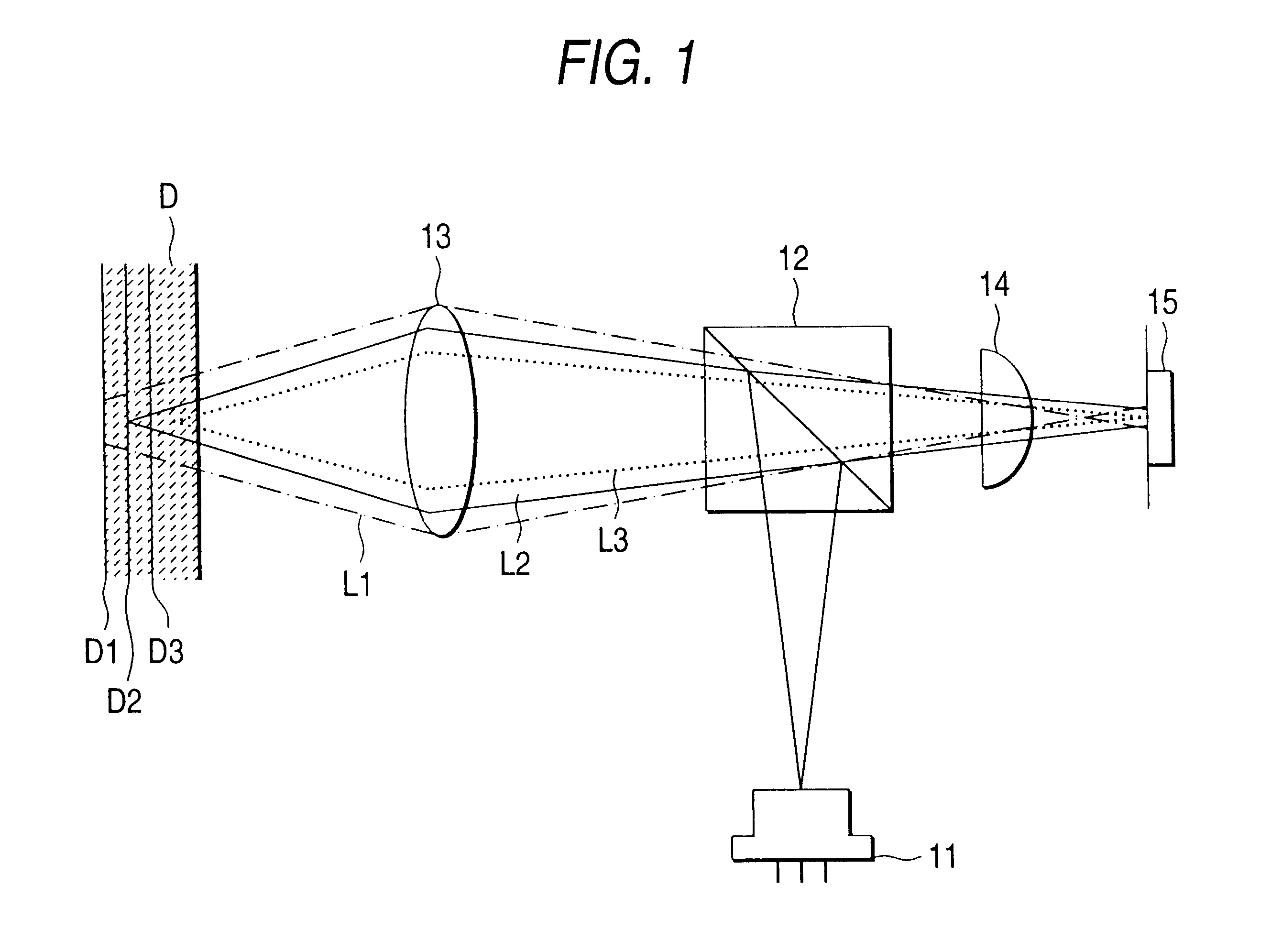
Thus, a converging position transforming device typically composed of a hologram device is used to separate the reflected light from the information bearing surface where information is to be reproduced and the reflected light from other information bearing surfaces and this ensures that only the signal component from the information bearing surface where information is being reproduced and which contains a reduced amount of the signal component from other surfaces is extracted with a simple structural design.

Problems solved by technology

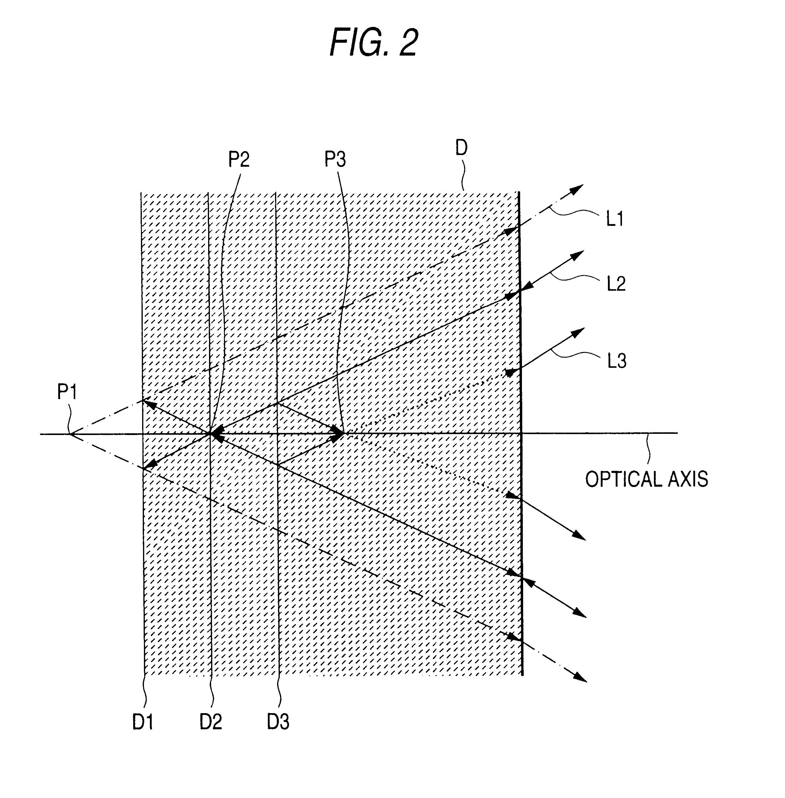
A problem with this method of converging a light beam on one information be aring surfaces is that the reflected light from the other information bearing surface is out of focus when it overlaps the reflected light from said one information bearing surface, thus producing playback noise.
If more than two recording layers are placed in superposition with a view to increasing the recording density, more light is reflected from information bearing surfaces other than where the incident light beam is converged and this further contributes to increased noise.
Since the light beam converging on the nearest surface has been modulated to high frequency, it will generate particularly great noise.

Method used


Image

  • Optical pickup
  • Optical pickup
  • Optical pickup

Examples


second example

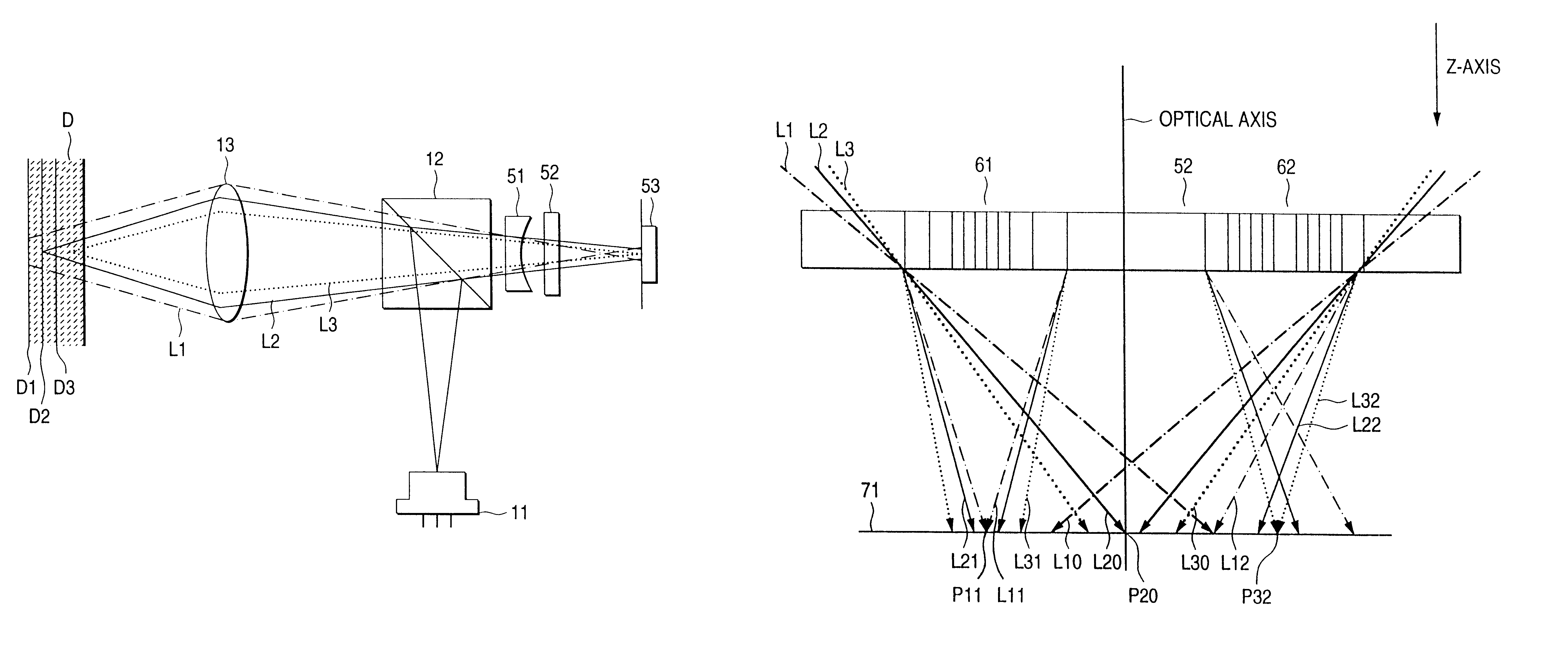
The description of the first example is directed to the method by which the crosstalk from an information bearing surfaces adjacent to the one from which information is to be reproduced is removed or attenuated by introducing astigmatism to reflected light components. The same effect can be attained by a non-astigmatic method. FIG. 5 shows the second example of the optical pickup of the present invention. As shown, the pickup of the second example comprises a semiconductor laser 11, a beam splitter 12 that splits an ongoing optical path from a return optical path, an objective lens 13, a concave lens 51 for extending the focal length of reflected light, a hologram device 52 for separating the reflected light into three spots that are defocused in different amounts, and a detector 53. The light beam issuing from the semiconductor laser 11 is converged on either one of the three information bearing surfaces D1, D2 and D3 of a multi-optical disk D having the same multi-layered structur...

third example

The first and second examples assume removing the crosstalk from the two information bearing surfaces that are adjacent to the surface where the recorded information is to be reproduced. This is not the sole case of the invention and the two examples may be applied in such a way as to remove the crosstalk from more than two information bearing surfaces.

FIG. 9 shows the third example of the optical pickup of the present invention. As shown, the pickup of the third example comprises a semiconductor laser 11, a beam splitter 12 for splitting an ongoing optical path from a return optical path, an objective lens 13, a second beam splitter 91 for separating the reflected light from an optical disk D into two components, a first and a second cylindrical lens 92 and 93 for introducing astigmatism into the separated components of the reflected light, and detectors 94 and 95 for detecting the separated components of the reflected light. The light beam issuing from the semiconductor laser 11 i...


PUM


Abstract

In an optical pickup, the focal position of the reflected light from the information bearing surface where information is to be reproduced and that of the reflected light from other information bearing surfaces are adjusted by an optical device such that the two reflected light components are separated optically.

Description

1. Field of the InventionThe present invention relates to an apparatus for reproducing video, audio and other signals that are recorded in optical recording media such as an optical disk. More particularly, the invention relates to an optical pickup which is used to reproduce information from a multi-layer recording medium including alternating half-mirror type and full-mirror type reflective recording layers and which is capable of attenuating the optical noise due to reflection from layers other than where information is being reproduced.2. Description of the Related ArtA practice recently adopted to increase the recording capacity per surface of an optical disk such as DVD (digital versatile disk) includes forming two recording layers by evaporating a half-mirror type reflective film on the top and a full-mirror type reflective film on the bottom. In a playback mode, a light beam is converged on either one of the information bearing surfaces of the recording layers and the reflec...

Claims


Application Information

Patent Timeline
IPC IPC(8): G11B7/135G11B7/13G11B7/00G11B7/12G11B7/133G11B7/1353G11B7/1372
CPCG11B7/133G11B7/1353G11B7/1372G11B2007/0013
Inventor MAEDA, TAKANORIARAKI, YOSHITSUGUKOYANAGI, HAJIME
Owner PIONEER CORP
Learn More