
Orthodontic distalizing appliance

a distalizing appliance and orthodontic technology, applied in the field of applications, can solve the problems of limited adjustment capability and considerably more complicated structural arrangement of parts of .s. pat. no. 5, and achieve the effect of convenient use and low manufacturing cos

Inactive Publication Date: 2002-08-20
WALDE KEVIN C
View PDF18 Cites 51 Cited by
  • Summary
  • Abstract
  • Description
  • Claims
  • Application Information

AI Technical Summary

Benefits of technology

The appliance provides advantages which are desirable in a successful distalizing device namely the utilization of an anchoring base such as a Nance button or palatal implant to provide superior anchorage of the appliance; predictable results with a minimum of undesirable side effects; easy accessibility to the adjustment device and ready replacement of the force-applying spring assembly and an overall reduction in patient chair time.
This orthodontic distalizing appliance is relatively inexpensive to manufacture, easy to use and efficient in performing its intended purpose.

Problems solved by technology

Hilgers' appliance is an important improvement to the dental art but has limited adjustment capability.
The appliance of U.S. Pat. No. 5,785,520 is considerably more complicated in its structural arrangement of parts than the Hilger's appliance and requires adjustment on both sides of the appliance.
None of the known prior art appliances incorporates a centrally located threaded adjustment feature for applying a variable force on the molars to which distalizing forces are applied.

Method used


Image

  • Orthodontic distalizing appliance
  • Orthodontic distalizing appliance
  • Orthodontic distalizing appliance

Examples


Embodiment Construction

:

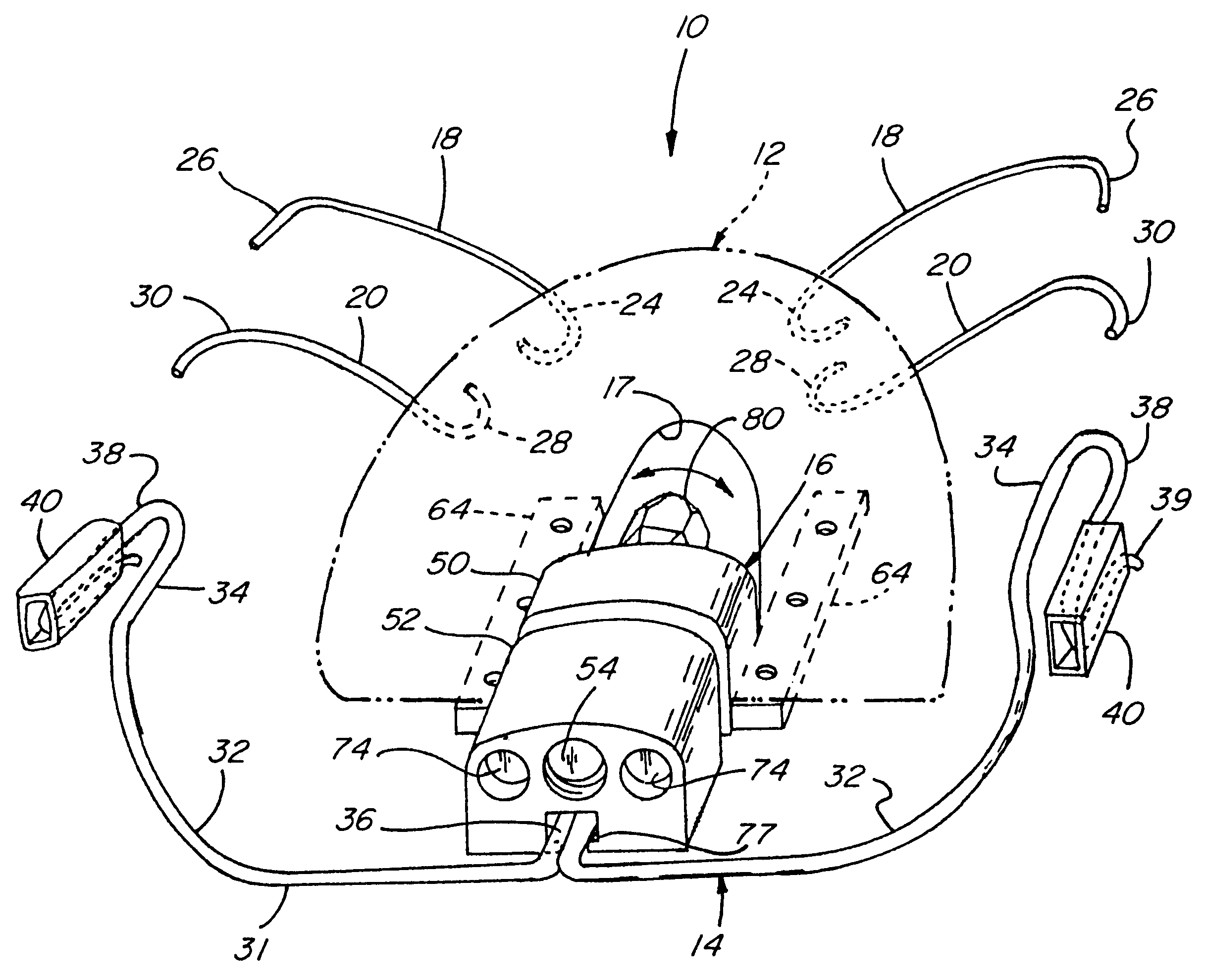
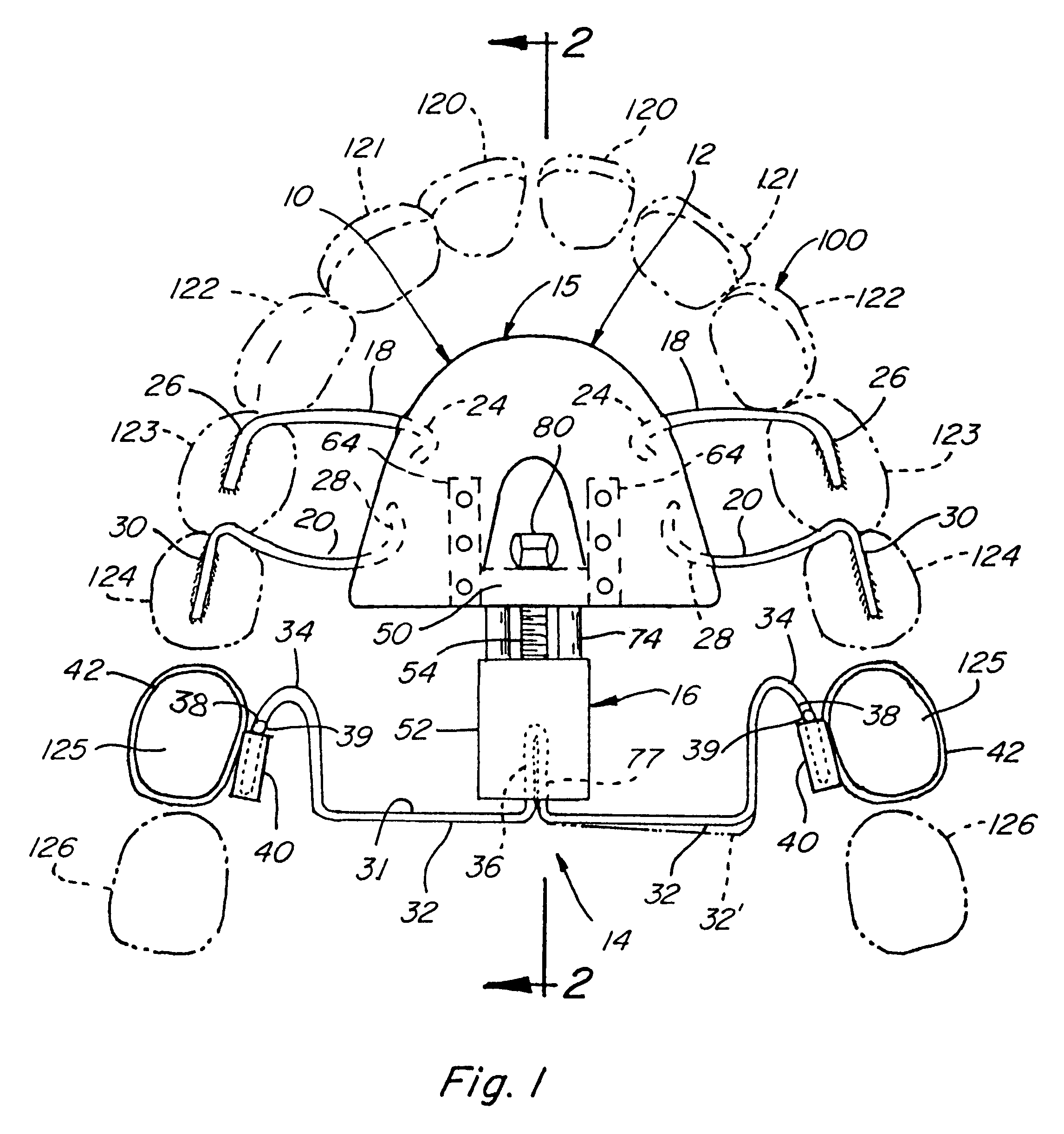
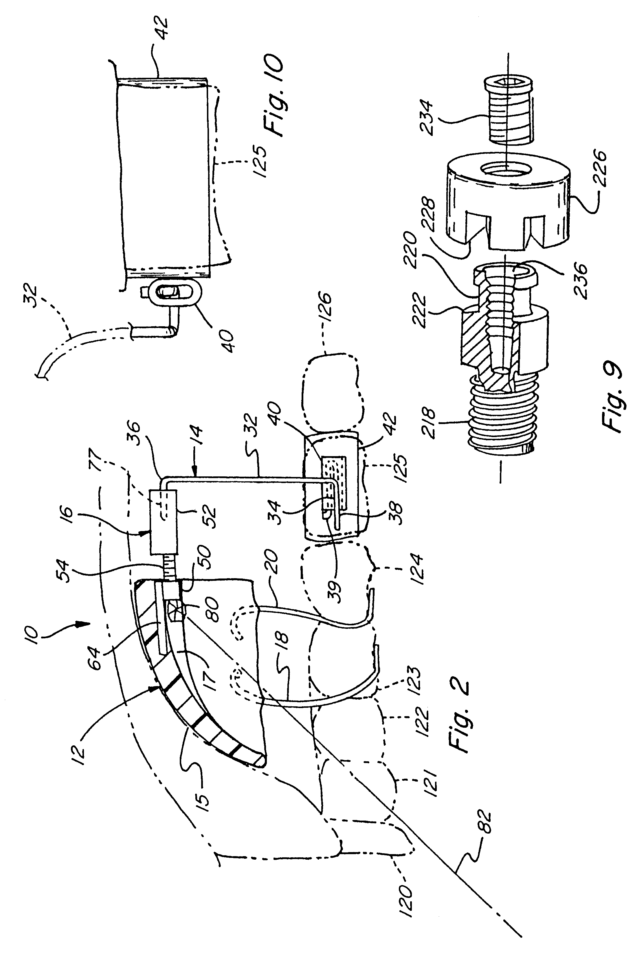
Referring now by reference numerals to the drawings and first to FIGS. 1-3, it will be understood that the appliance 10 is intended for the purpose of distalizing molars by the application of a controlled pressure from a substantially fixed Nance button or other anchoring device such as an endosseous implant.

The appliance 10 is used in the area of the mouth generally known as the maxillary dental arch, more specifically the palate, indicated by numeral 100 and having a plurality of teeth arranged in an arch formation about the roof of the mouth and more particularly the palatal zone 102. The dental arch is further defined by the basal gingiva which provides a base for opposed sets of teeth consisting of the incisors 120 and 121, the canines 122, the premolars or bicuspids 123 and 124 and the molars 125 and 126.

The appliance 10 includes essentially a forwardly disposed support anchorage assembly 12, a spring assembly 14 and an adjustment device 16 which extends between a Nance butto...


PUM


Abstract

This orthodontic distalizing appliance includes a forward support assembly having an anchoring base in the roof of the mouth. A rearward laterally disposed spring assembly is provided having outer ends removably received within associated sheaths attached to maxillary molars. A centrally disposed adjustment assembly extends between the anchoring base and the spring assembly for applying a force to the spring assembly which is transmitted to the molars to be distalized.

Description

BACKGROUND OF THE INVENTION:This invention relates generally to appliances for correcting malocclusion problems by non-extraction molar distalization methods and in particular to an appliance which uses a forward anchorage assembly, a rearward spring assembly and a threadedly adjustable device extending between the forward and rearward assemblies for achieving distalization.One of the most well-known appliances used in modern orthodontics for correcting class II malocclusions is the Pendulum Appliance described by James J. Hilgers in the November 1992 issue of the Journal of Clinical Orthodontics in an article entitled The Pendulum Appliance for Class II Non-Compliance Therapy pp. 706-714, which is incorporated herein by reference. The Pendulum Appliance uses a large Nance acrylic button in the palatal area which is anchored by a wire attachment assembly to the upper premolars, in combination with a spring assembly which is attached between the mid-point of the button and the first ...

Claims


Application Information

Patent Timeline
Patent Type & Authority Patents(United States)
IPC IPC(8): A61C7/00A61C7/10A61C7/08A61C8/00
CPCA61C7/00A61C7/10A61C8/0096
Inventor WALDE, KEVIN C.
Owner WALDE KEVIN C
Learn More