
Device for drilling and draining holes in soil or rock

a technology for draining devices and drilling holes, applied in the direction of drilling pipes, drilling well accessories, cutting machines, etc., can solve the problems of partial enlargement of drill hole diameters, deviation from the optimum drilling direction, and inability to selective dewatering or draining

Inactive Publication Date: 2002-08-13
ALWAG TUNNELAUSBAU GMBH
View PDF15 Cites 16 Cited by
  • Summary
  • Abstract
  • Description
  • Claims
  • Application Information

AI Technical Summary

Benefits of technology

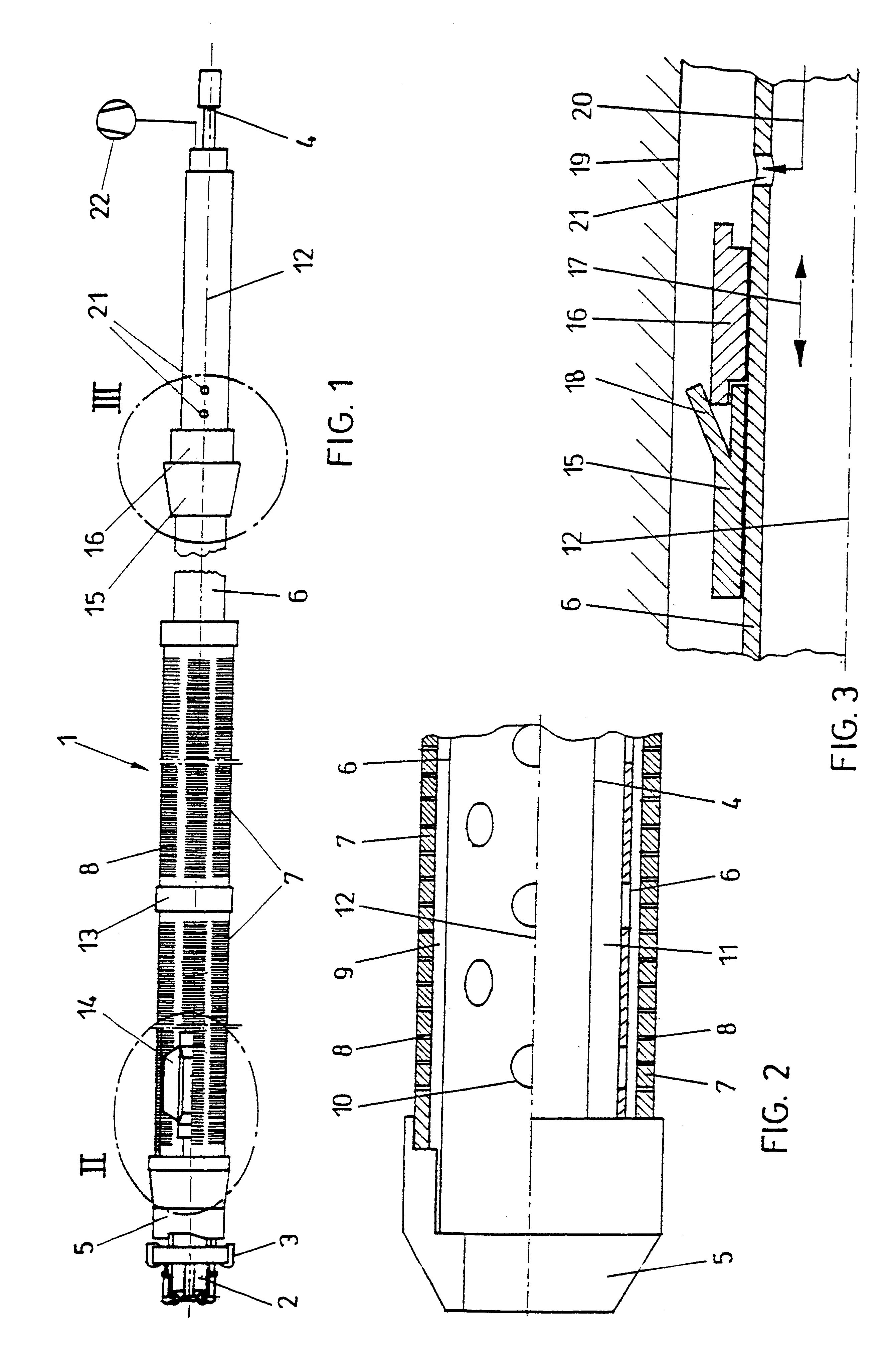
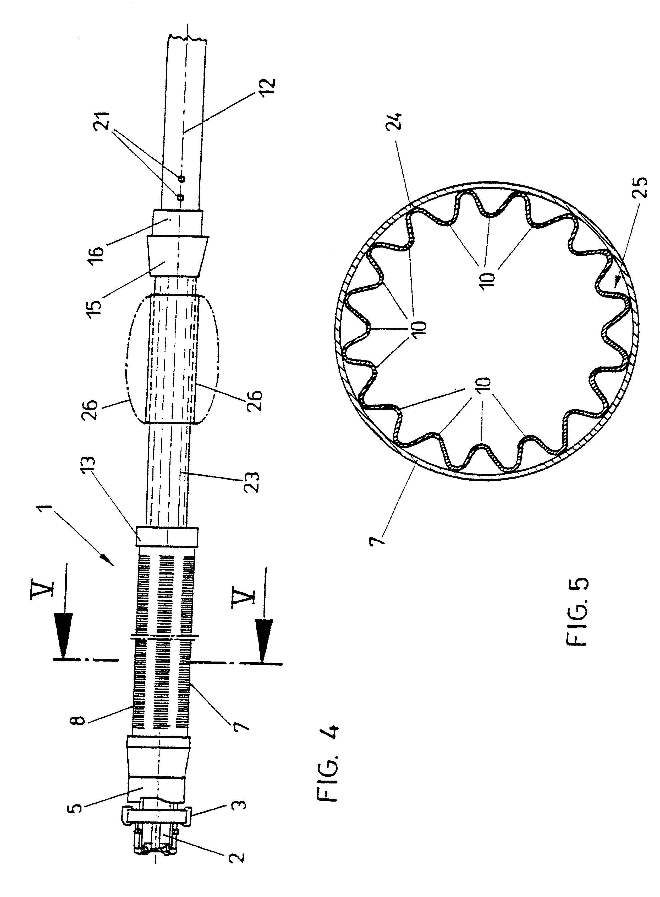
In order to enable the proper passage through the filtering tube of the liquid to be drained, it is provided that the annular space formed between the external circumference of the jacket tube and the internal diameter of the filtering tube has a clear passage width of at least 1 mm and, in particular, about 1.5 mm, as in correspondence with a further preferred embodiment of the device according to the invention. Such a clear passage cross section or dimensioning of the annular space provided between the external circumference of the jacket tube and the internal circumference of the filtering tube usually will be sufficient to enable the proper drainage of the fluid to be drained into the interior of the jacket tube, while simultaneously ensuring that no excessive enlargement, or no enlargement at all, of the drill hole diameter or drill hole cross section will be become necessary during the production of the drill hole in order to take into account the additional dimensions of the jacket-tube-surrounding filtering tube to be inserted so as to avoid any additional extra expense for realizing a bore.
If the arrangement of one or several filtering tubes over a larger longitudinal extension of the jacket tube in the region following upon the drill bit is desired, it is, moreover, provided in a preferred manner that the annular space is defined by spacers arranged between the jacket tube and the filtering tube and / or by sleeve elements provided, in particular, in the end regions of the filtering tube such that the annular space required between the jacket tube and the filtering tube for a proper filter effect even over larger lengths of a filtering section will be safely maintained.
In particular, when providing a filtering tube having a larger longitudinal extension or when providing several contiguous filtering tubes in order to be able to provide an accordingly long draining or dewatering path, it is contemplated according to another preferred embodiment that the jacket tube in its section surrounded by the filtering tube is provided with a plurality of passage openings arranged distributedly about its circumference, particularly in a uniform manner, the clear width of which passage openings exceeds the clear width of the passage openings or slits formed in the filtering tube so as to enable an accordingly safe extraction of the fluid through the annular space provided between the jacket tube and the drill rod assembly. By dimensioning the passage openings or slits on the circumference of the jacket tube accordingly larger, the possibility of an immediate transportation of the fluid will, moreover, be ensured even when providing a smaller amount of passage openings or slits. Obstruction of the passage openings or slits provided in the jacket tube need not be feared in that case, since the filtering tube is designed with accordingly smaller passage openings or slits so that the entry of larger particles need not be feared. Furthermore, it is also feasible by an appropriate distribution of the passage openings or slits in the jacket tube to devise the configuration in a manner that no excessive weakening of the mechanical strength or resistance of the jacket tube need be feared.
In order to assist any desired drainage, it is suggested according to a further preferred embodiment that a sealing element is provided on the external circumference of the jacket tube at a distance from the filtering tube on the end facing away from the drill bit and that in the jacket tube, on the end facing away from the filtering tube, at least one outlet opening for delivering a filling mass, in particular a hardening suspension, is provided in the vicinity of the sealing element. By means of such a sealing element, which enables the sealing of a drill hole relative to surrounding rock, in particular upon delivery of the filling mass, in particular a hardening suspension such as, for instance, concrete or the like, not only the path or length of the drill hole provided for draining will be precisely defined, but such sealing also prevents fluid possibly present in the region of the drill bit from spreading within the drill hole along the external side of the jacket tube, thereby causing, for instance, the flushing, or undesired enlargement of the dimensions, of the drill hole as might be feared, for instance, at the occurrence of water with a roof bolt to be set in a roof, in which case the drill hole opening extends inclinedly downwards and fluid present in the rock could flow off outside the jacket tube.
In order to enable accordingly simple sealing, the configuration preferably is devised such that the sealing element is comprised of a lip-shaped or tongue-shaped synthetic element annularly surrounding the jacket tube and capable of being widened upon introduction of the filling mass, wherein, in this respect, it is, furthermore, suggested in a preferred manner that the sealing element is formed with a hardness of 80 to 100 Shore and, in particular, 90 Shore. While maintaining a suitable mechanical strength or resistance of the sealing element, this also results in the respective elasticity allowing for proper widening, and hence abutting of the sealing element on the wall of the produced drill hole, upon introduction of a filling mass.

Problems solved by technology

However, when doing so, it is to be anticipated that selective dewatering or draining is impossible not least for the reason that the at least one passage opening provided in the region immediately following upon the drill bit serves to remove the worked material and, therefore, must have an accordingly large cross section naturally unable to provide for the respective filter effect required in draining.
In particular with drillings in loose rock or in rock layers of varying compositions, partial enlargements of the drill hole diameters may optionally result from deviations from the optimum drilling direction, which in some cases may not be completely compensated for or reliably sealed by the sealing element.

Method used


Image

  • Device for drilling and draining holes in soil or rock
  • Device for drilling and draining holes in soil or rock
  • Device for drilling and draining holes in soil or rock

Examples


Embodiment Construction

In FIG. 1, a device for drilling, in particular impact drilling or rotary percussion drilling, and draining holes in soil or rock material is generally denoted by 1, wherein a drill bit, which is divided into a central drill bit 2 and an annular drill bit 3, for instance, in the radial direction, in a known manner is actuated for impact drilling or rotary percussion drilling via a drill rod assembly schematically indicated by 4. The drill bit, in addition, cooperates with an impact shoe 5, wherein the drill rod assembly 4 is surrounded by a jacket tube 6 composed of several individual parts, as will be apparent even more clearly from FIGS. 2 and 3.

In the region immediately following upon the drill bit 2, 3 and the impact shoe 5, respectively, a filtering tube 7 surrounding the jacket tube 6 and composed of a plurality of individual parts in the shown representation is provided, which comprises a plurality of passage openings or passage slits 8 distributed about its periphery, partic...


PUM


Abstract

The invention relates to a device (1) for the drilling, notably by percussion or rotary-percussion drilling, and draining of holes in soil or rock. A drill bit (2, 3) mounted on a drill rod (4) creates a bore hole and a jacket tube (6) is coupled to the drill rod (4) or the drill bit (2, 3). In the area adjacent to the drill bit (2, 3) the jacket tube (6) has at least one through hole which opens into an annular space embodied between the drill rod and the jacket tube. In the end area adjacent to the drill bit (2, 3) the jacket tube (6) is surrounded by at least one filter tube (7) having a plurality of through holes or slits (8) which are distributed especially evenly across its circumference. This allows for correspondingly safe and reliable drainage during boring, using simple measures.

Description

1. Field of the InventionThe present invention relates to a device for drilling, in particular impact drilling or rotary percussion drilling, and draining holes in soil or rock material, wherein a drill bit mounted on a drill rod assembly forms a drill hole and a jacket tube is coupled with the drill rod assembly or the drill bit, wherein the jacket tube in the region following upon the drill bit is formed with at least one passage opening that opens into an annular space formed between the drill rod assembly and the jacket tube.2. Description of the Prior ArtA device of this type can be taken, for instance, from WO 98 / 21439, wherein a process and a device for simultaneously drilling and lining holes is disclosed. By means of a jacket tube surrounded by a drill rod assembly actuating a drill bit, an annular space is made available between the jacket tube and the external periphery of the drill rod assembly, wherein, for instance, in the region immediately following upon the drill bi...

Claims


Application Information

Patent Timeline
Patent Type & Authority Patents(United States)
IPC IPC(8): E21B7/20E21B43/02E21B43/10E02D3/00E02D3/10E21B43/08
CPCE02D3/10E21B7/20E21B43/10
Inventor MOCIVNIK, JOSEFBOHM, KARL
Owner ALWAG TUNNELAUSBAU GMBH
Learn More