
Methods and apparatus for mixing of liquids

a technology of liquid mixing and mixing chamber, which is applied in the field of methods and apparatus for mixing liquids, can solve the problems of fluid exiting the housing and insufficient to cause the fluid to exit the housing

Inactive Publication Date: 2005-04-21
AGILENT TECH INC
View PDF33 Cites 23 Cited by
  • Summary
  • Abstract
  • Description
  • Claims
  • Application Information

AI Technical Summary

Benefits of technology

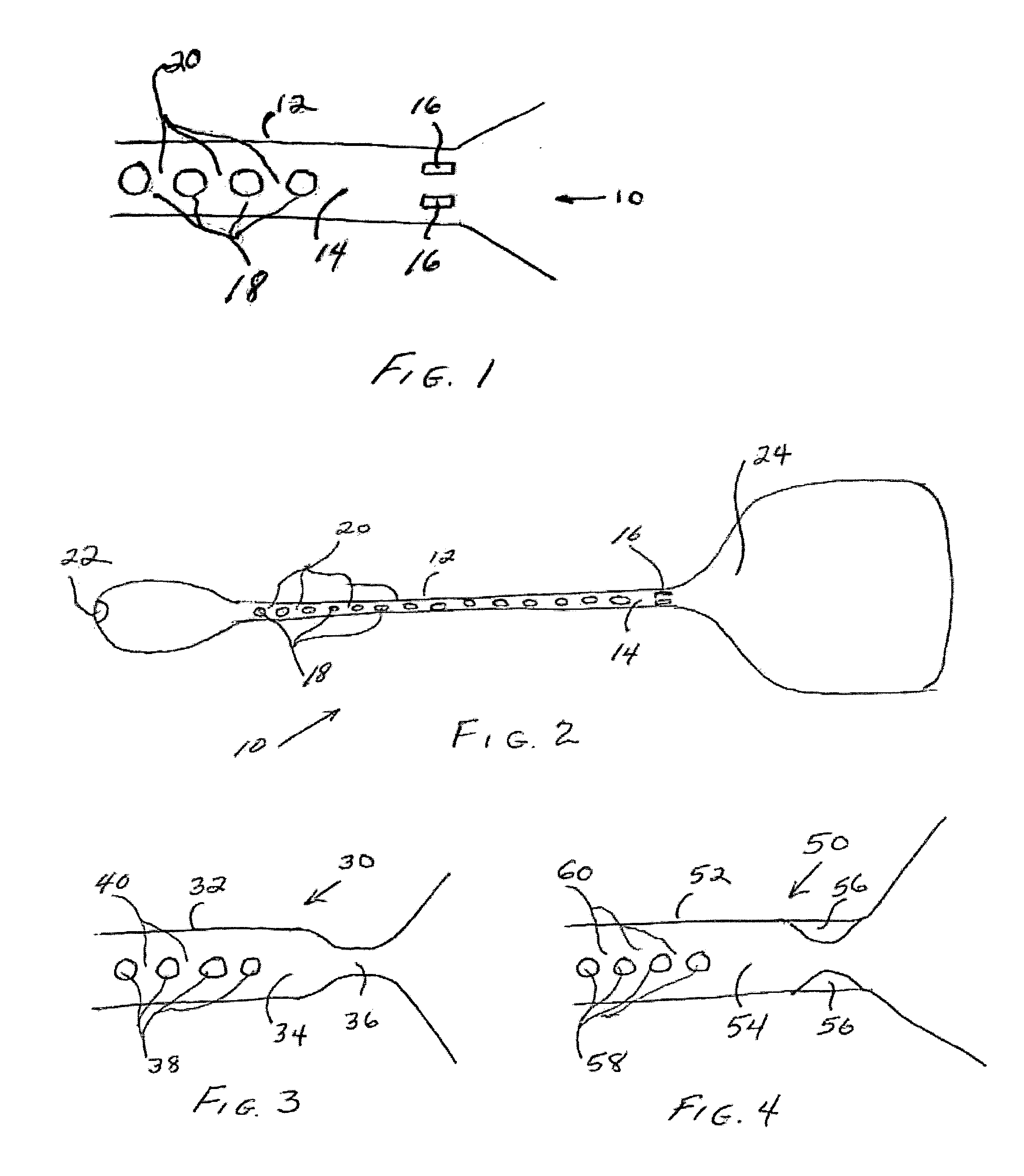
[0018] Another embodiment of the present invention is a method for conducting hybridization reactions. A sample is introduced into a housing comprising a linear microarray of features for hybridizing to analytes in the sample and a mixing area. The housing has internal capillary dimensions and a structural member in the interior adjacent an end of the housing. The dimensions of and placement of the structural member are sufficient such that intermittent application of centrifugal force to the interior causes motion of the fluid in the housing. The sample is incubated in the housing under conditions for carrying out the hybridization reactions. During the incubation intermittent centrifugal force is generated to cause reciprocal movement of the fluid between the linear array and the mixing area but insufficient to cause the fluid to exit the housing. Rotating the housing may generate the intermittent centrifugal force. Optionally, the centrifugal force may be increased to a level sufficient to cause the fluid to exit the interior. A wash fluid may be introduced into the housing and intermittent centrifugal force may be generated sufficient to cause movement of the wash fluid but insufficient to cause the wash fluid to exit the housing. Optionally, the centrifugal force may be increased to a level sufficient to cause the fluid to exit the interior.

Problems solved by technology

The method comprises introducing a fluid into a housing of an apparatus as described above and generating intermittent centrifugal force to cause movement of the fluid but insufficient to cause the fluid to exit the housing.
During the incubation intermittent centrifugal force is generated to cause reciprocal movement of the fluid in the interior of the housing between the linear array and the mixing area but insufficient to cause the fluid to exit the housing.

Method used


Image

  • Methods and apparatus for mixing of liquids
  • Methods and apparatus for mixing of liquids
  • Methods and apparatus for mixing of liquids

Examples


Embodiment Construction

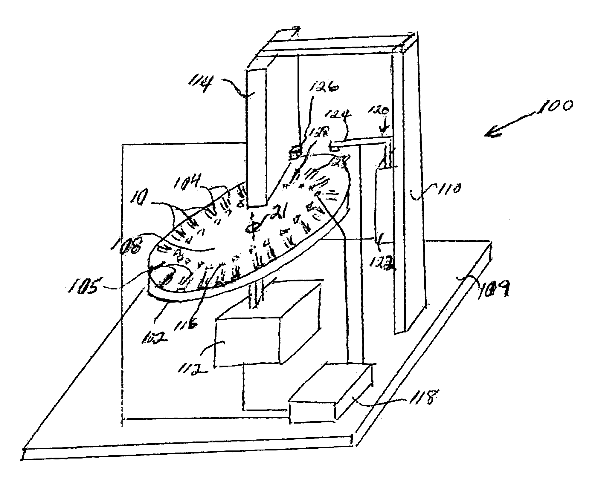
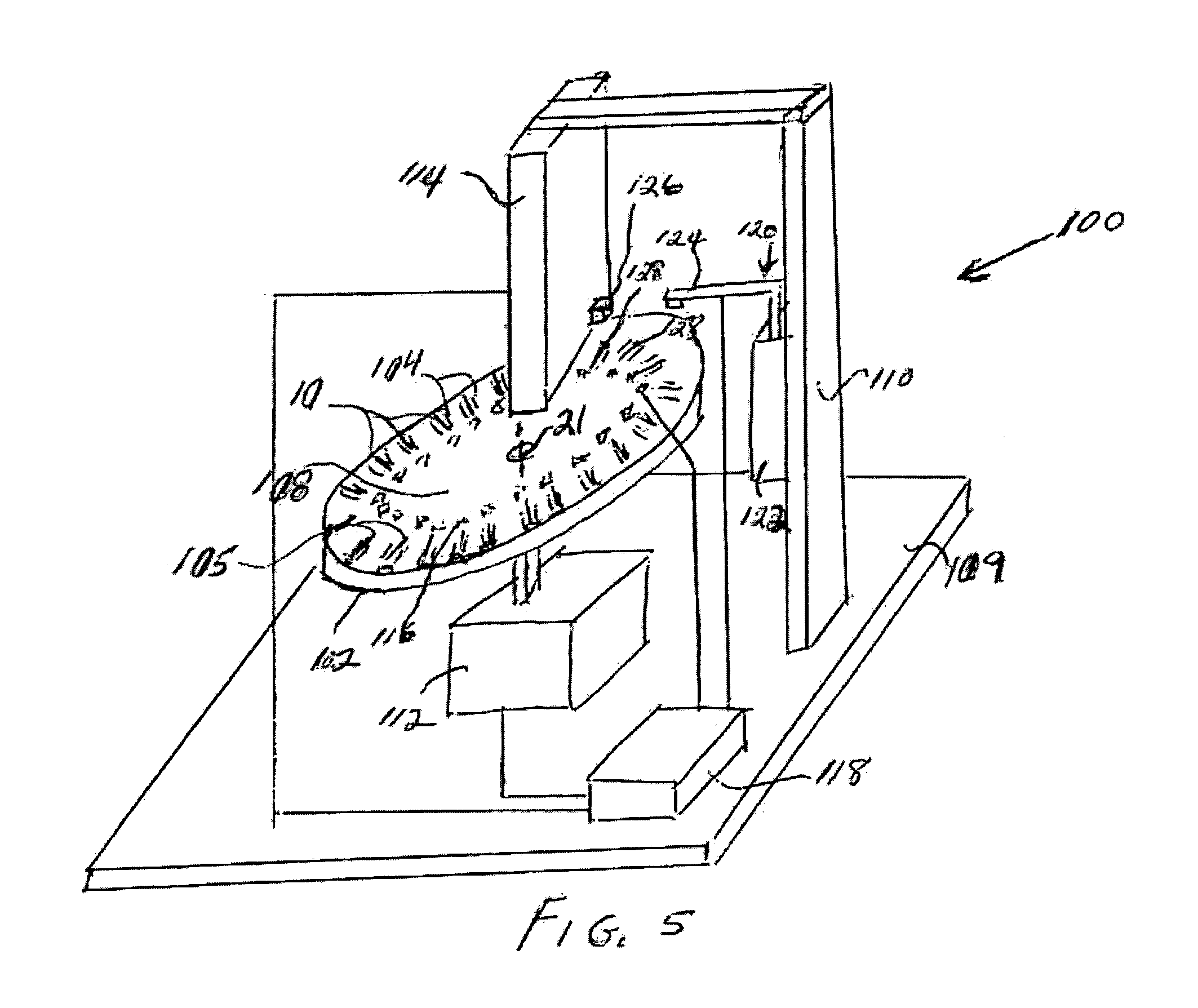
[0025] The present invention utilizes a capillary valve and centrifugal force to induce mixing in fluids. In one embodiment the capillary valve may comprise small structural members, which essentially act as a capillary leash, i.e., a way of controlling the movement of fluid in a capillary environment. Centrifugal force may be employed to move fluid in a capillary channel within a housing while retaining the fluid within the channel or to move the fluid to a mixing area and back to the channel. To remove fluid from the channel, the centrifugal force is increased to a level to overcome the capillary forces within the channel. The centrifugal force may be applied to the channel by rotating the channel.

[0026] The present invention provides a multi-function valve that acts as a leash to control movement of the fluid within a capillary environment and to control exit of fluid from the capillary environment. The valve may be fabricated at the same time as the fabrication of the capillary...


PUM

PropertyMeasurementUnit
diameteraaaaaaaaaa
diameteraaaaaaaaaa
diameteraaaaaaaaaa

Abstract

An apparatus for mixing fluids comprises a housing having at least a portion of its interior, for example, a channel, with capillary dimensions and at least one structural member in the interior adjacent an end of the channel. The dimensions of and placement of the structural member are sufficient such that intermittent application of centrifugal force to the interior of the housing causes movement of the fluid therein. The housing may comprise a mixing chamber or area that is in fluid communication with the interior. The apparatus may comprise a mechanism adapted to generate centrifugal force within the housing to cause movement of fluid in the interior of the housing without exit of fluid therefrom.

Description

BACKGROUND OF THE INVENTION [0001] The present invention relates to apparatus and methods for conducting chemical and biological analyses using linear arrays. More particularly, the invention relates to apparatus and methods for carrying out mixing operations in hybridization reactions using linear microarrays. The invention has utility in fields relating to biology, chemistry and biochemistry. [0002] Determining the nucleotide sequences and expression levels of nucleic acids (DNA and RNA) is critical to understanding the function and control of genes and their relationship, for example, to disease discovery and disease management. Analysis of genetic information plays a crucial role in biological experimentation. This has become especially true with regard to studies directed at understanding the fundamental genetic and environmental factors associated with disease and the effects of potential therapeutic agents on the cell. Such a determination permits the early detection of infec...

Claims


Application Information

Patent Timeline
Patent Type & Authority Applications(United States)
IPC IPC(8): B01F5/06B01F13/00B01F15/02B01L3/00C40B60/14G01N35/00G01N35/04
CPCB01F5/061Y10S366/01B01F15/0201B01F15/0233B01F2005/0621B01F2005/0636B01F2215/0431B01J2219/00326B01J2219/0052B01J2219/00657B01J2219/00702B01L3/50273B01L2200/10B01L2300/0636B01L2300/0806B01L2300/0867B01L2400/0409B01L2400/0688B01L2400/086C40B60/14G01N2035/00237G01N2035/0449Y10S366/03B01F13/0059B01F25/4317B01F25/431971B01F33/30B01F35/71B01F35/71725B01F35/7547B01F35/71805
Inventor CAREN, MICHAEL P.SCHEMBRI, CAROL T.
Owner AGILENT TECH INC
Learn More