
Electro-optic ice detection device

a detection device and optical technology, applied in the field of ice detection, can solve the problems of increasing the risk of flying, ice and ice buildup has been blamed for numerous accidents, and ice poses a significant problem, and achieves the effect of simple optical

Inactive Publication Date: 2002-07-30
AEROMECHANICAL SERVICES
View PDF11 Cites 48 Cited by
  • Summary
  • Abstract
  • Description
  • Claims
  • Application Information

AI Technical Summary

Benefits of technology

to provide a simple optical detection system that can detect the presence and thickness of ice. It is another object of the invention to detect the presence and thickness of ice irrespective of the roughness of the formed ice or imperfections in the ice scattering the light. It is an object of this invention to distinguish between fluid and ice. Finally, it is an object of the invention to determine when ice thickness has reached a critical depth.

Problems solved by technology

Ice poses a significant problem in the transportation industry.
Throughout the years, numerous accidents have been attributed to ice and ice buildup.
With respect to aviation, ice has the ability to compromise airworthiness by changing the flight characteristics and the weight of an airplane, thereby increasing the risk of flying.
Often pilots are not aware of the onset of airframe icing until the safety of the flight is in jeopardy.
These devices suffer from serious technical limitations due to roughness of the ice surface and imperfections in the ice scattering the light.
As ice develops on the recessed surface, ice will obstruct the beam detector, such that the beam will no longer be detectable by the beam detector.
The electromagnetic wavelength of the beams is selected such that a thin layer of ice, water or de-icing / anti-icing fluid on the walls of the recess surface will not produce sufficient optical attenuation to trigger ice or contamination indications.

Method used


Image

  • Electro-optic ice detection device
  • Electro-optic ice detection device
  • Electro-optic ice detection device

Examples


Embodiment Construction

. The invention is described using two beams, however the invention will work with one or more beams.

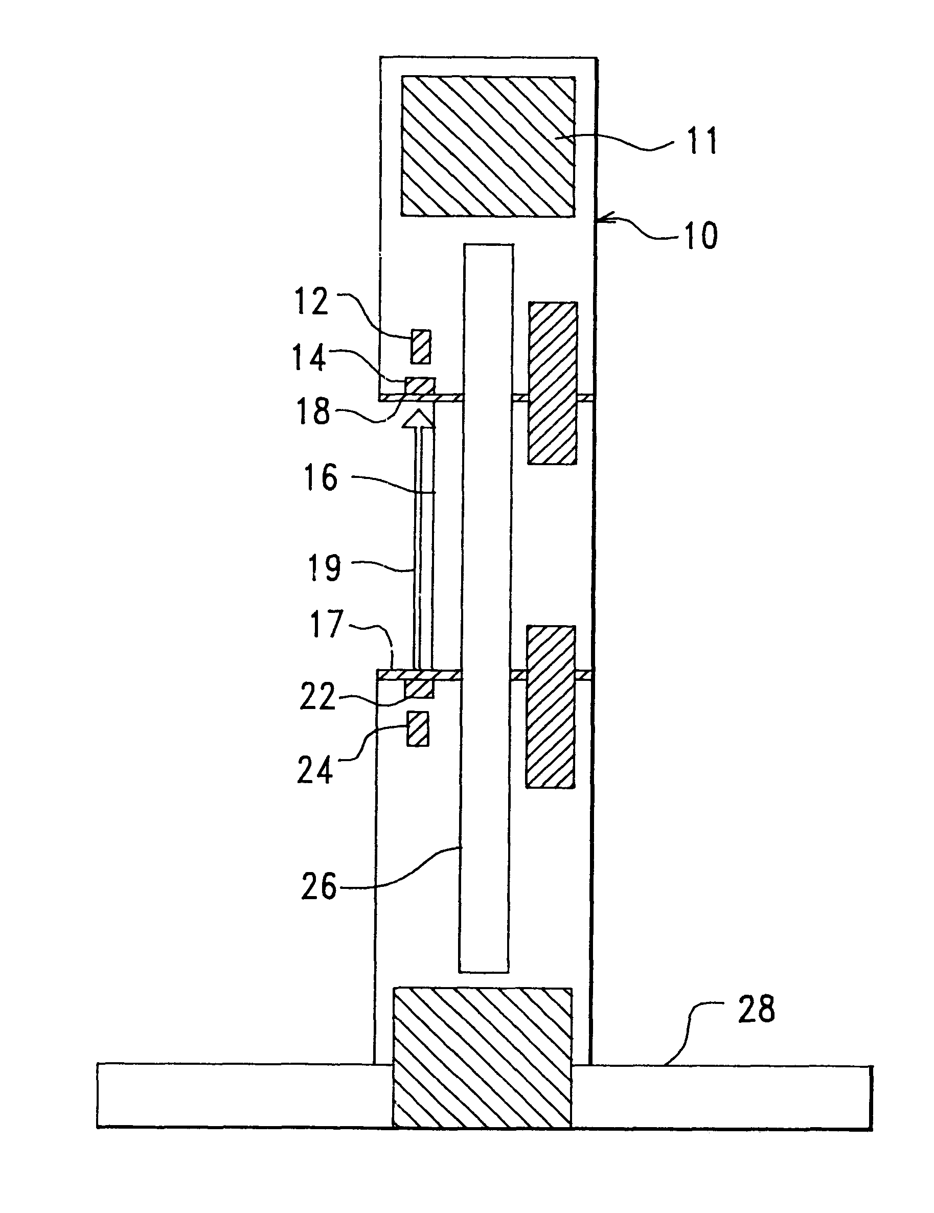
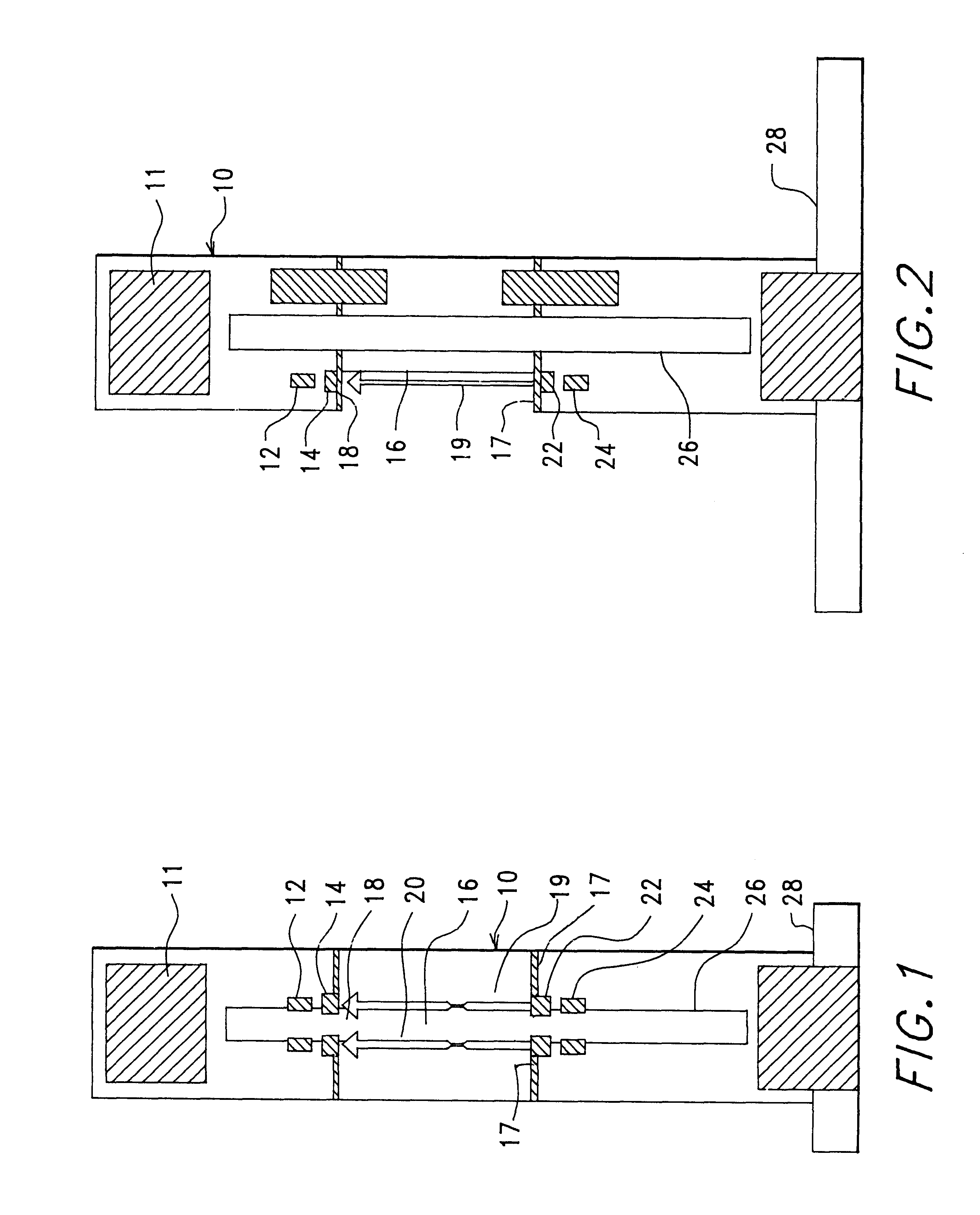
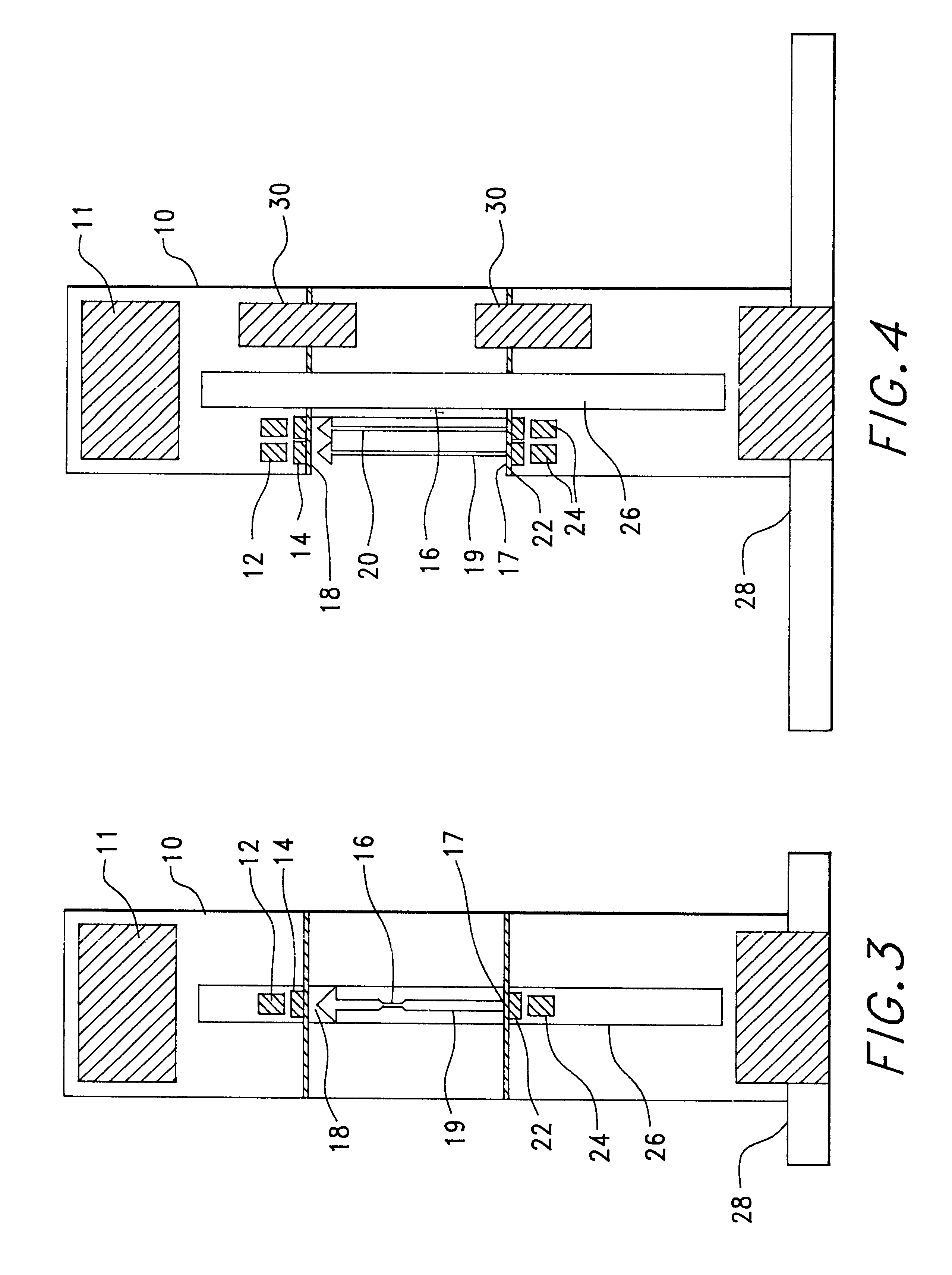
FIG. 1 is a front view of the Ice Detection Probe and shows the Housing 10, Wiring Cavity 11, Beam Detector 12, Optical Filter 14, Recessed surface including a base portion 16, First side portion 17, Second side portion 18, Beam 119, Beam 220, Transparent Windows 22, Emitters 24, Heater 26, and the Attachment Plate 28. FIG. 2 is a side view of the Ice Detection Probe and shows the Housing 10, Wiring Cavity 11, Beam Detector 12, Optical Filter 14, Recessed surface base portion 16, First side portion 17, Second side portion 18, Beam 119, Transparent Windows 22, Emitters 24, Heater 26, and the Attachment Plate 28 The Beam 1, 19, and Beam 2, 20 at the same depth. For best results the beams are 0.02 inches above the Recessed Surface base portion 16.

FIG. 3 is a front view of the second preferred embodiment and shows the Housing 10, wiring Cavity 11, Infrared Beam Detector 12, Optical Filte...


PUM


Abstract

The present invention is an optical ice detection probe capable of detecting the presence, thickness and continued buildup of ice. The invention works by attaching the probe to the external surface of an airplane such as the wing, fuselage or empannage. The probe has a recessed surface, which is mounted to face directly into the airflow. One or more beams are passed over and parallel to the recessed surface. These beams can be of any useful wavelength, however for best results visible, infrared or ultraviolet beams should be used. Ice on the recessed surface interrupts the beams thereby indicating the presence of ice. If two or more beams are used, then each beam emitter is paired with a beam detector and the corresponding beam detector only detects the beam from that emitter. This can be accomplished by numerous methods. For example, powering each beam emitter alternately and sampling the output of the corresponding detector, electronically modulating the beam to a specific frequency with corresponding detectors designed to respond to the specific frequency or using an optical filter that passes only specific wavelengths.

Description

1. Field of the InventionThe present invention relates to the field of ice detection and more particularly to a new and improved device for optically detecting the presence and thickness of ice.2. Discussion of the Prior ArtIce poses a significant problem in the transportation industry. Throughout the years, numerous accidents have been attributed to ice and ice buildup. With respect to aviation, ice has the ability to compromise airworthiness by changing the flight characteristics and the weight of an airplane, thereby increasing the risk of flying. Often pilots are not aware of the onset of airframe icing until the safety of the flight is in jeopardy. Thus, an icing detection system that alerts pilots to the initial onset of icing is desirable. Furthermore, the optimal use of in-flight de-icing equipment such as aircraft de-icing boots often depends upon the depth of ice buildup. Thus, the need exists for a reliable and affordable means to detect ice and to assess the buildup of i...

Claims


Application Information

Patent Timeline
Patent Type & Authority Patents(United States)
IPC IPC(8): B64D15/00B64D15/20
CPCB64D15/20
Inventor ANDERSON, MARKMEINERS, LARRY
Owner AEROMECHANICAL SERVICES
Learn More