
Developing device and image forming apparatus having a restricted developer surface level feature

a technology of developing device and developer surface, which is applied in the direction of electrographic process apparatus, instruments, optics, etc., can solve the problems of uneven image density at the screw pitch, difficult to circulate the developer in a satisfactory manner, and so on

Inactive Publication Date: 2002-07-16
CANON KK
View PDF11 Cites 50 Cited by
  • Summary
  • Abstract
  • Description
  • Claims
  • Application Information

AI Technical Summary

Problems solved by technology

The above-described conventional developing device, however, has a problem that it is sometimes difficult to circulate the developer in a satisfactory manner depending on long-duration operation and environmental conditions.
This causes the so-called screw pitch unevenness, i.e., unevenness in image density at the screw pitch.
Such a phenomenon causes problems that the toner is hard to evenily mix with the developer and the toner not yet electrically charged is supplied to the development chamber 50A, thus resulting in fogging or density failure.
Accordingly, when the sensor surface 56a is not completely covered with the developer, variations in sensor output are remarkably increased, thus resulting in an unsatisfactory result.
Also, if the developer surface in the agitation chamber 50B is inclined, a charging capability as a result of friction would be deteriorated.
Eventually, the method cannot satisfy the above-described fourth condition and gives rise to a density difference in the longitudinal direction.
In other words, controlling the developer surface level in a proper range to satisfy the above-mentioned first to fourth conditions has been hitherto impossible to realize in practice.
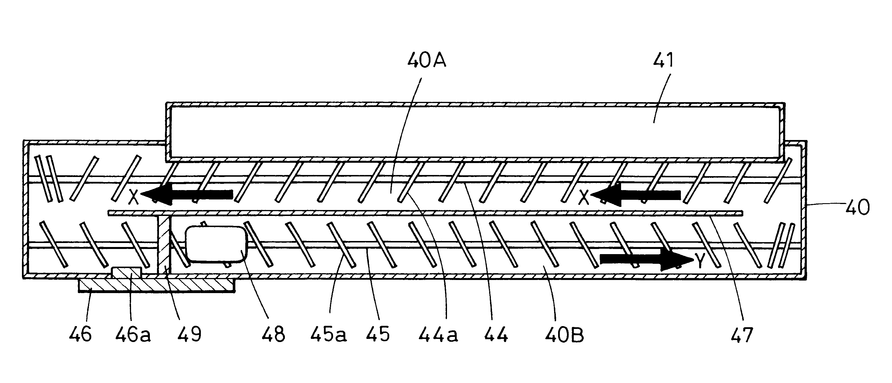
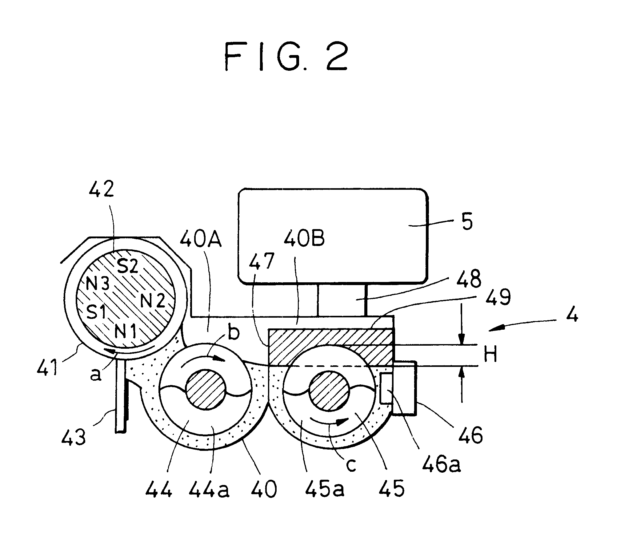
If the developer surface level in the agitation chamber 40B is lower than such an allowable lower limit position, an unsatisfactory result would be caused because a detection level of the toner density sensor 46 varies.
This gives rise to an unsatisfactory result of causing the so-called screw pitch unevenness, i.e., unevenness in image density at the screw pitch.
However, the problems of unevenness in image density and fogging occurred in Comparative Examples not including the developer flow restricting member 49.

Method used


Image

  • Developing device and image forming apparatus having a restricted developer surface level feature
  • Developing device and image forming apparatus having a restricted developer surface level feature
  • Developing device and image forming apparatus having a restricted developer surface level feature

Examples


second embodiment

An image forming apparatus of second embodiment is basically the same as that of first embodiment. Therefore, components in second embodiment having the identical function and construction to those in first embodiment are denoted by the same symbols and a detailed description thereof is omitted here.

FIG. 5 schematically shows the construction of the developing device of this embodiment as viewed from above. In the above-described first embodiment, the developer flow restricting member 49 is provided downstream of the toner density sensor 46 in the direction of transport of the developer. In this second embodiment, a developer flow restricting member 49 is provided upstream of a toner density sensor 46 in the direction of transport of the developer. The developer flow restricting member 49 is the same as that used in above first embodiment.

By providing the developer flow restricting member 49 upstream of the toner density sensor 46 in the direction of transport of the developer, this...


PUM


Abstract

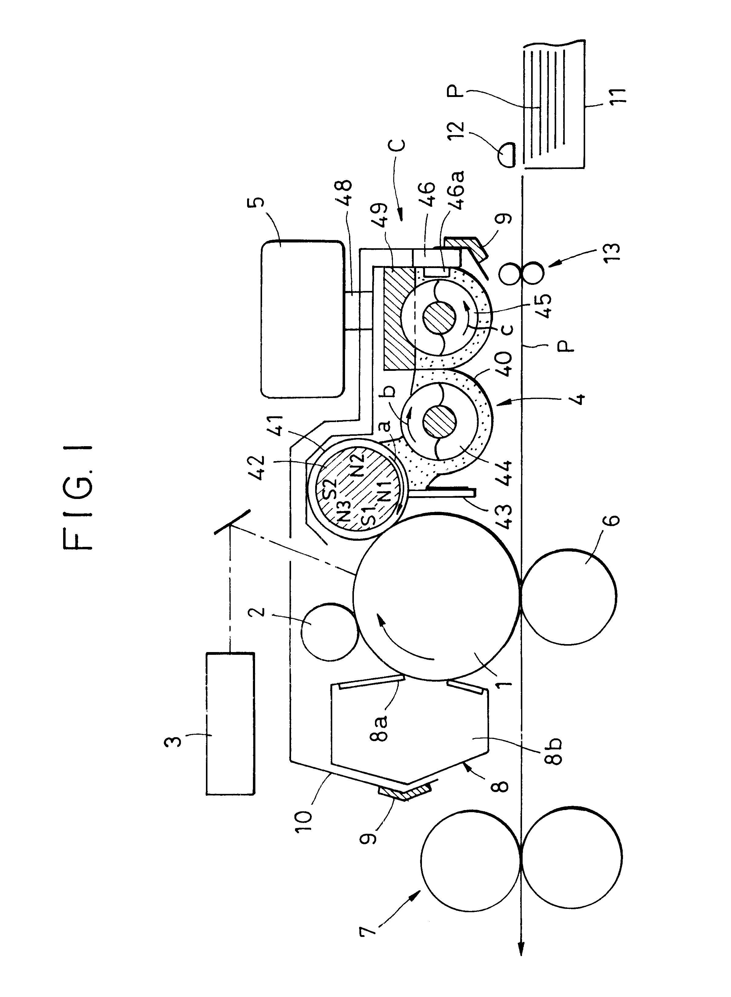
A developing device and an image forming apparatus includes a developer container for containing a developer made up of magnetic particles and a toner; a developer carrier for bearing and transporting the developer; a first agitating and transporting unit provided in the developer container, the first agitating and transporting unit transporting the developer while agitating the developer; a second agitating and transporting unit provided in the developer container, the second agitating and transporting unit transporting the developer transported by the first agitating and transporting unit while agitating the developer, thereby supplying the developer to the developer carrier; and a restricting member provided in the developer container, the restricting member restricting passage of an upper portion of the developer transported by the first agitating and transporting unit, thereby achieving a desired developer surface level.

Description

1. Field of the InventionThe present invention relates to a developing device and an image forming apparatus in which an electrostatic latent image is formed on an image carrier with a electrophotographic process or an electrostatic recording process, for example, and then developed using a two-component developer. Further, the present invention relates to a process cartridge and an electrophotographic image forming apparatus to which the process cartridge is mounted in a detachable manner.Herein, the terms "image forming apparatus" and "electrophotographic image forming apparatus" include, for example, copying machines, printers (such as an LED printer and a laser beam printer), facsimiles, word processors, etc.Also, the term "process cartridge" implies not only an integral unit comprising at least one of a charging means, developing means, and cleaning means, and an electrophotographic photoconductor, which are constructed in the form of a cartridge, the cartridge being detachably...

Claims


Application Information

Patent Timeline
IPC IPC(8): G03G15/08
CPCG03G15/0822G03G2215/0822
Inventor KINOSHITA, MASAHIDEYAMAGUCHI, SEIJIADACHI, MOTOKI
Owner CANON KK
Learn More